
Automobile chassis bearing square tube machining mechanism

A processing mechanism and automobile chassis technology, applied in the direction of manufacturing tools, other manufacturing equipment/tools, etc., can solve the problems of laborious, labor-intensive, large volume and weight of square tubes, etc.

Active Publication Date: 2021-09-03
枣庄群鑫金属制造股份有限公司
View PDF15 Cites 0 Cited by
  • Summary
  • Abstract
  • Description
  • Claims
  • Application Information

AI Technical Summary

Problems solved by technology

[0002] With the development of industrial technology, modern automobile industry technology has become more and more perfect. In the process of automobile manufacturing, it is necessary to make automobile chassis. The automobile chassis needs to be built with load-bearing square tubes. Due to the relatively large weight of the automobile, it is convenient to The side wall thickness of the tube is relatively large, and the volume and weight of the square tube are relatively large. When the tube is loaded, the staff needs to manually carry it. This kind of loading operation is laborious, and the accuracy of manual loading is not high enough; It is necessary to open a hole during processing. In the past, a punching machine was required to punch out a hole. However, after the punching machine is processed, a curved flange will be left on the workpiece. This curved flange is not conducive to assembly. For other parts, if holes of different diameters need to be made on the workpiece, the stamping die at the output end of the stamping machine needs to be replaced frequently, which is very labor-intensive

Method used


Image

  • Automobile chassis bearing square tube machining mechanism
  • Automobile chassis bearing square tube machining mechanism
  • Automobile chassis bearing square tube machining mechanism

Examples


Embodiment Construction

[0028] In order to make the object, technical solution and advantages of the present invention clearer, the present invention will be further described in detail below in conjunction with the accompanying drawings and embodiments. It should be understood that the specific embodiments described here are only used to explain the present invention, not to limit the present invention.

[0029] In describing the present invention, it should be understood that the terms "longitudinal", "transverse", "upper", "lower", "front", "rear", "left", "right", "vertical", The orientations or positional relationships indicated by "horizontal", "top", "bottom", "inner", "outer", etc. are based on the orientations or positional relationships shown in the drawings, and are only for the convenience of describing the present invention, rather than indicating or It should not be construed as limiting the invention by implying that a referenced device or element must have a particular orientation, be...


PUM


Abstract

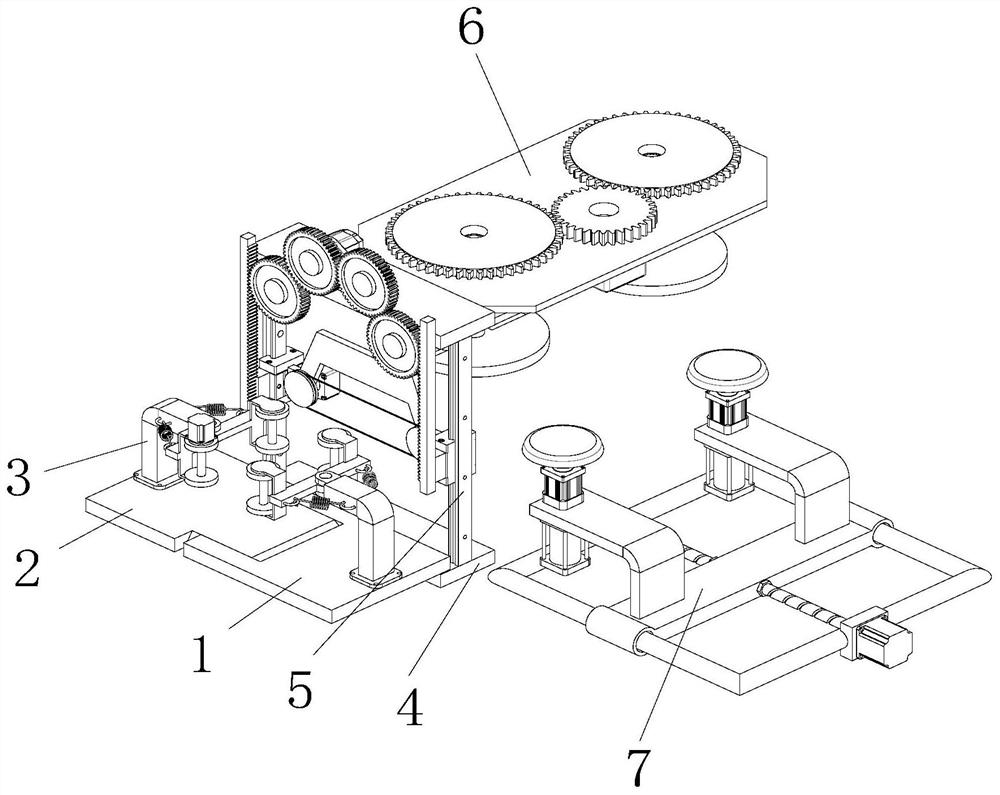
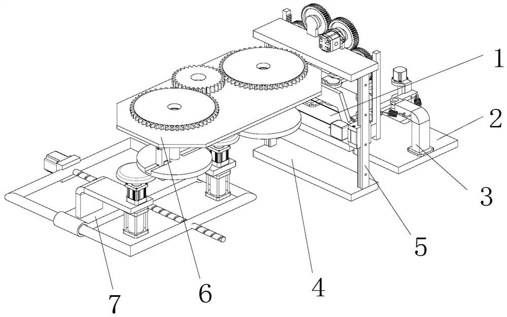
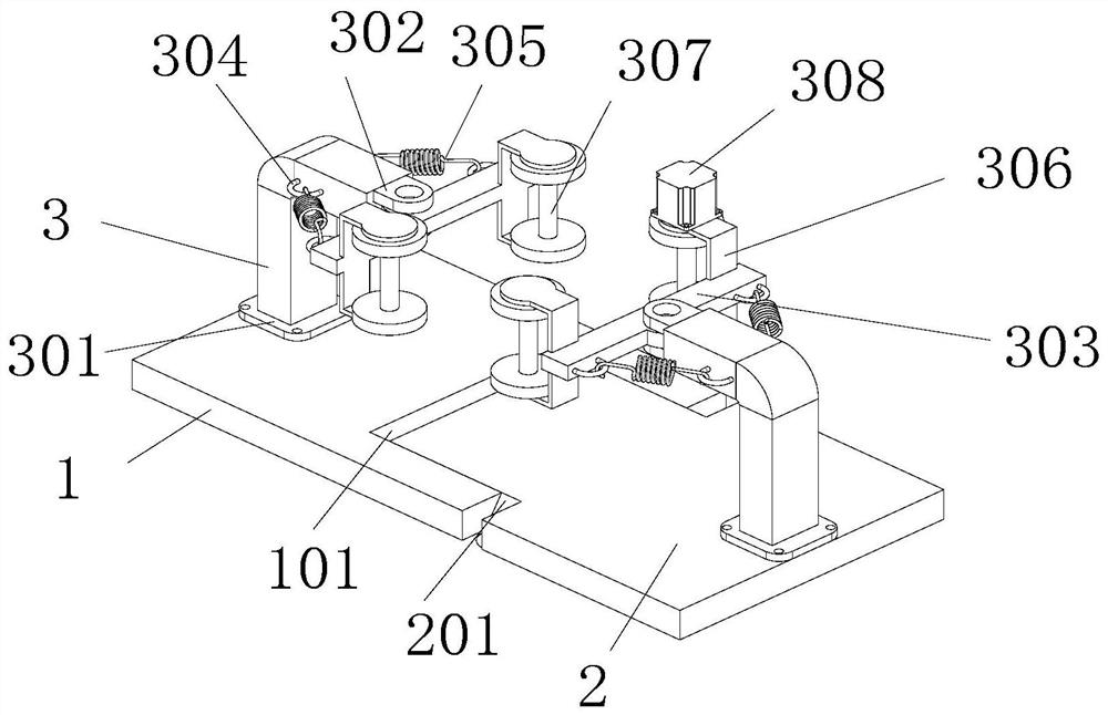
The invention discloses an automobile chassis bearing square tube machining mechanism, and belongs to the field of automobile machining. The automobile chassis bearing square tube machining mechanism comprises a base table plate, a dismounting table is arranged at one side of the base table plate, a penetrating groove is formed at one side of the base table plate, and a penetrating strip is arranged at one side of the dismounting table; and the penetrating strip is arranged at the inner side of the penetrating groove in a penetrating manner, and is in sliding connection with the penetrating groove. The bottom end of the base table plate is provided with two locking nuts, the inner sides of the locking nuts are provided with screw valves, the inner sides of the locking nuts are provided with through holes, and the ends of the screw valves penetrate through the through holes at the inner sides of the locking nuts and are attached to the side wall of the penetrating strip; and two bearing tables are arranged at one side of the base table plate and one side of the dismounting table, two vertical guide rails are arranged between the bearing tables, a machining assembly is arranged at the sides, away from the base table plate and the dismounting table, of the vertical guide rails, and a grinding assembly is arranged below the machining assembly. The distance between the dismounting table and the base table plate can be adjusted.

Description

technical field [0001] The invention relates to the field of automobile processing, in particular to a processing mechanism for a load-bearing square tube of an automobile chassis. Background technique [0002] With the development of industrial technology, modern automobile industry technology has become more and more perfect. In the process of automobile manufacturing, it is necessary to make automobile chassis. The automobile chassis needs to be built with load-bearing square tubes. Due to the relatively large weight of the automobile, it is convenient to The side wall thickness of the tube is relatively large, and the volume and weight of the square tube are relatively large. When the tube is loaded, the staff needs to manually carry it. This kind of loading operation is laborious, and the accuracy of manual loading is not high enough; It is necessary to open a hole during processing. In the past, a punching machine was required to punch out a hole. However, after the pu...

Claims


Application Information

Patent Timeline
Patent Type & Authority Applications(China)
IPC IPC(8): B23P23/04
CPCB23P23/04Y02W30/56
Inventor 金香花
Owner 枣庄群鑫金属制造股份有限公司
Learn More