Balance car wheel and balance car thereof
A balance car and wheel technology, applied in the field of balance cars, can solve the problems of inability to realize modular and fast installation, high production cost of the balance car, and complicated installation steps of the balance car, so as to solve the complicated installation steps, improve the waterproof performance, and shorten the length. Effect
- Summary
- Abstract
- Description
- Claims
- Application Information
AI Technical Summary
Problems solved by technology
Method used
Image
Examples
Embodiment 1
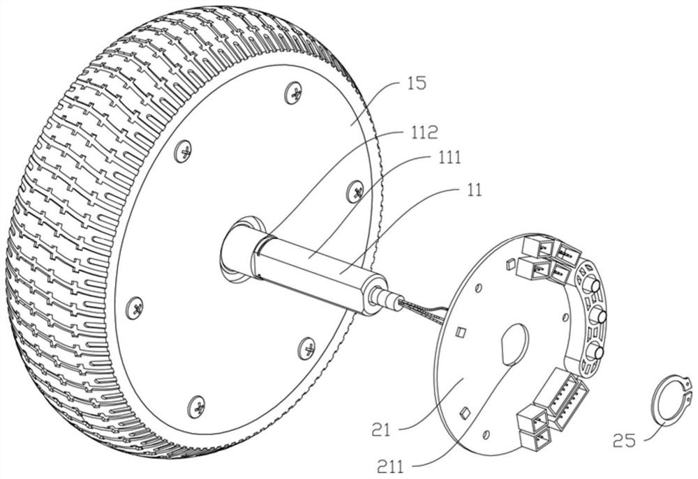
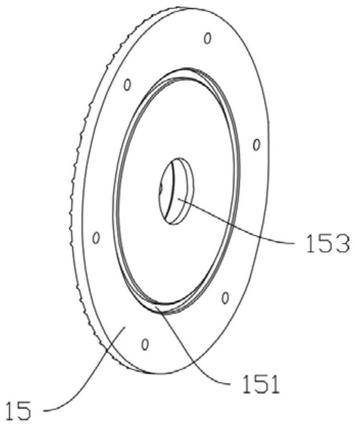
[0086] as attached figure 1 As shown, in this embodiment, the controller is a circuit board structure, including the control circuit board 21 and the components on it, the installation part includes the flat mouth structure 211 and the fixing part 25 in the middle of the control circuit board 21, and the through hole of the motor shaft 11 There is a step 112 on the exit end 111, and the shape of the flat mouth structure 211 is adapted to the shape of the exit end 111. Position against the step 112 under the action. In a specific embodiment, there is a certain distance between the step 112 and the inner end cover 15, so that the controller is kept at a certain distance from the rotating inner end cover 15 to protect the controller.
[0087] Preferably, the fixing member 25 can be a circlip, and correspondingly, a positioning groove for fixing the circlip is provided on the exit end 111 of the motor shaft 11; or, the fixing member 25 can be a nut, and the exit end 111 of the mo...
Embodiment 2
[0094] Based on the above-mentioned embodiment, the difference between this embodiment and Embodiment 1 is that the installation part includes a fixed seat, and the controller is a control circuit board structure, including a control circuit board and components on it. The exit end is fixedly connected, and other structures are the same as those in Embodiment 1.
[0095] as attached Figure 4 And attached Figure 5 As shown, the fixed seat 23 of the present embodiment is elongated, and the fixed seat 23 is elongated, and the center is provided with a flat mouth structure, which is used for the fixed connection of the passing end 111 of the motor shaft 11. The fixed seat 23 is provided with a The first flat groove 231 fitted with the motor shaft 11 makes the fixing seat 23 and the motor shaft 11 relatively stationary; the edge of the first flat groove 231 is provided with a first protrusion 232, and the first protrusion 232 protrudes toward the inner end cover Setting, the fi...
Embodiment 3
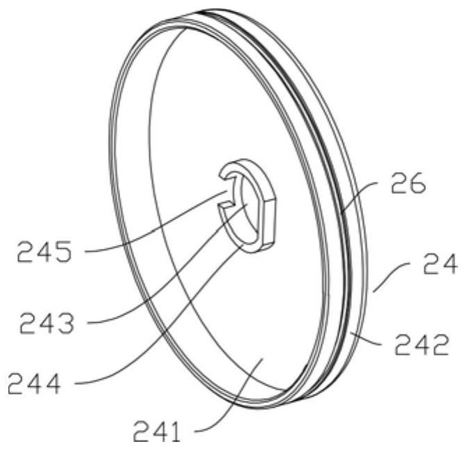
[0098] as attached Image 6 And attached Figure 7 As shown, in this embodiment, the controller is a circuit board structure, including a control circuit board 21 and components on it, and the installation part includes a fixing seat 23, the controller is fixedly connected to the fixing seat 23, and the fixing seat 23 is connected to the motor shaft 11 The piercing end 111 is fixedly connected. as attached Image 6 As shown, the controller is fixed on the fixed seat 23, and the fixed seat 23 is fixedly connected with the passing end 111 of the motor shaft 11. The advantage of this embodiment is that it avoids excessive processing of the control circuit board 21 of the controller, and the fixed seat 23 It can be processed by injection molding to reduce costs. Preferably, the fixing seat 23 can be made of heat insulating material, so as to prevent the motor shaft 11 from conducting the heat of the hub motor to the controller.
[0099] In this embodiment, as attached Image ...
PUM
 Abstract
Description
Claims
Application Information
 - R&D
- Intellectual Property
- Life Sciences
- Materials
- Tech Scout
- Unparalleled Data Quality
- Higher Quality Content
- 60% Fewer Hallucinations
Browse by: Latest US Patents, China's latest patents, Technical Efficacy Thesaurus, Application Domain, Technology Topic, Popular Technical Reports.
© 2025 PatSnap. All rights reserved.Legal|Privacy policy|Modern Slavery Act Transparency Statement|Sitemap|About US| Contact US: help@patsnap.com


