Supercharge Your Innovation With Domain-Expert AI Agents!

Resin line formed from a corrugated pipe

A technology of resin tubes and corrugated tubes, applied in the direction of pipes/pipe joints/fittings, hoses, pipes, etc., can solve the problems of unfavorable imprinting and collapse of materials, and achieve the effect of simplifying diffusion

Pending Publication Date: 2021-09-03
FIBER COMPOSITES INNOVATIONS LLC
View PDF3 Cites 0 Cited by
  • Summary
  • Abstract
  • Description
  • Claims
  • Application Information

AI Technical Summary

Problems solved by technology

A resin line with an omega-shaped cross-section is also not particularly load-resistant, since it expands under pressure in the region of the longitudinal gap and then collapses
[0006] In the known bellows, the material footprint of the bellows in the matrix material of the component has proven to be disadvantageous

Method used


Image

  • Resin line formed from a corrugated pipe
  • Resin line formed from a corrugated pipe
  • Resin line formed from a corrugated pipe

Examples


Embodiment Construction

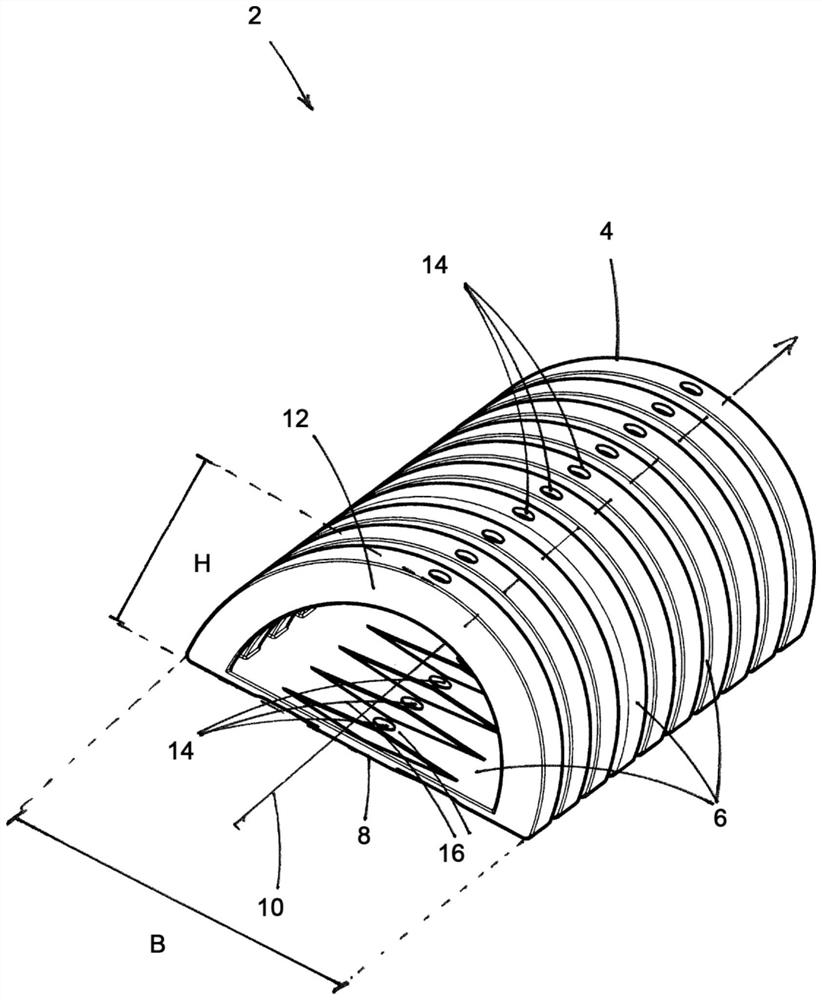
[0030] exist figure 1 The section of the resin line 2 formed by the bellows 4 is shown in . The corrugated tube 4 has a wall made of corrugated material. In this case, the corrugations can have a circular configuration or, as in the exemplary embodiment, have a corrugated angular cross-sectional shape. It is important that the wall 6 is not designed to be smooth, but the corrugated shape enables the bellows 4 to bend without kinks occurring in the wall 6 which would interfere with a good flow and could lead to the leakiness.

[0031] As can be seen from obliquely above in the view, the bellows 4 has a rotationally non-symmetrical cross-sectional shape transversely to the longitudinal center axis 10 due to the fact that the wall 6 is divided into two parts. In the first part, the wall 6 is provided along the circumference of the wall 6 with a truncated base 8 extending over the length of the bellows 4 in a direction transverse to the longitudinal center axis 10, and in the s...


PUM


Abstract

The invention relates to a resin line (2) formed from a corrugated pipe (4), which has individual through-holes arranged on the circumferential side in a wall (6). In order to improve the resin line (2), it is provided that the wall (6) of the bellows (4), which wall (6) is closed at least in sections, has a non-rotationally symmetrical cross-sectional shape transverse to the longitudinal center axis (10), the wall (6) being divided into a first part having a truncated base (8) extending over the length of the bellows (4) in a direction transverse to the longitudinal center axis (10), and a second part having an arc(12) extending in the length of the bellows (4) in a direction transverse to the longitudinal center axis (10) to a height (H), and for the cross-sectional shape, the width (B) of the truncated base (8) as the first part of the wall (6) is greater than the height (H) of the second part of the wall (6) which is configured as the arc (12).

Description

technical field [0001] The invention relates to a resin line formed by a bellows, which has in the wall individual through-holes arranged on the circumferential side. Background technique [0002] A vacuum infusion method is described, for example, in document DE 102 39 325 B4. To manufacture fiber composite components, resin lines are placed into the mold in order to convey the liquid matrix material under vacuum to the reinforcing fibers placed into the tool. Reinforcing fibers can be present as fiber semi-finished products in the form of rovings, mats, scrims (Gelege), textiles, multiaxial materials, knits and braids and are produced from a wide variety of fiber materials, such as carbon fibers, glass fibers, aramids Fibers, boron fibers or hybrid materials, any combination is also possible. Reinforcing fibers are impregnated with matrix material delivered through resin lines. Here too, the matrix material fills the mold. Various suitable resin systems can be used as ...

Claims


Application Information

Patent Timeline
Patent Type & Authority Applications(China)
IPC IPC(8): F16L11/11F16L11/15B29C70/54B29C70/48B29C70/44
CPCB29C70/62F16L11/11F16L11/15B29C70/54B29C70/48B29C70/44B29L2023/18B29C70/546B29C70/443
Inventor D·迪克斯
Owner FIBER COMPOSITES INNOVATIONS LLC
Features
  • R&D
  • Intellectual Property
  • Life Sciences
  • Materials
  • Tech Scout
  • Unparalleled Data Quality
  • Higher Quality Content
  • 60% Fewer Hallucinations
Learn More