Multi-light-source laser aircraft trajectory design method and system

An aircraft and laser technology, applied in the field of laser aircraft, can solve the problems of inconvenient overall design optimization, high time cost, etc., and achieve the effect of reducing design iteration time

Active Publication Date: 2021-09-03
BEIHANG UNIV
View PDF5 Cites 0 Cited by
  • Summary
  • Abstract
  • Description
  • Claims
  • Application Information

AI Technical Summary

Problems solved by technology

There are few ballistic design methods related to domestic laser aircraft, most of which are single-ground laser station design, and most of the existing design methods are to design and integrate each discipline separately. The coupling variables between disciplines need to be iterated multiple times, and the time cost is relatively high Large, inconvenient for overall design optimization
[0004] Since the way of laser propulsion to gen

Method used


Image

  • Multi-light-source laser aircraft trajectory design method and system
  • Multi-light-source laser aircraft trajectory design method and system
  • Multi-light-source laser aircraft trajectory design method and system

Examples


Embodiment 1

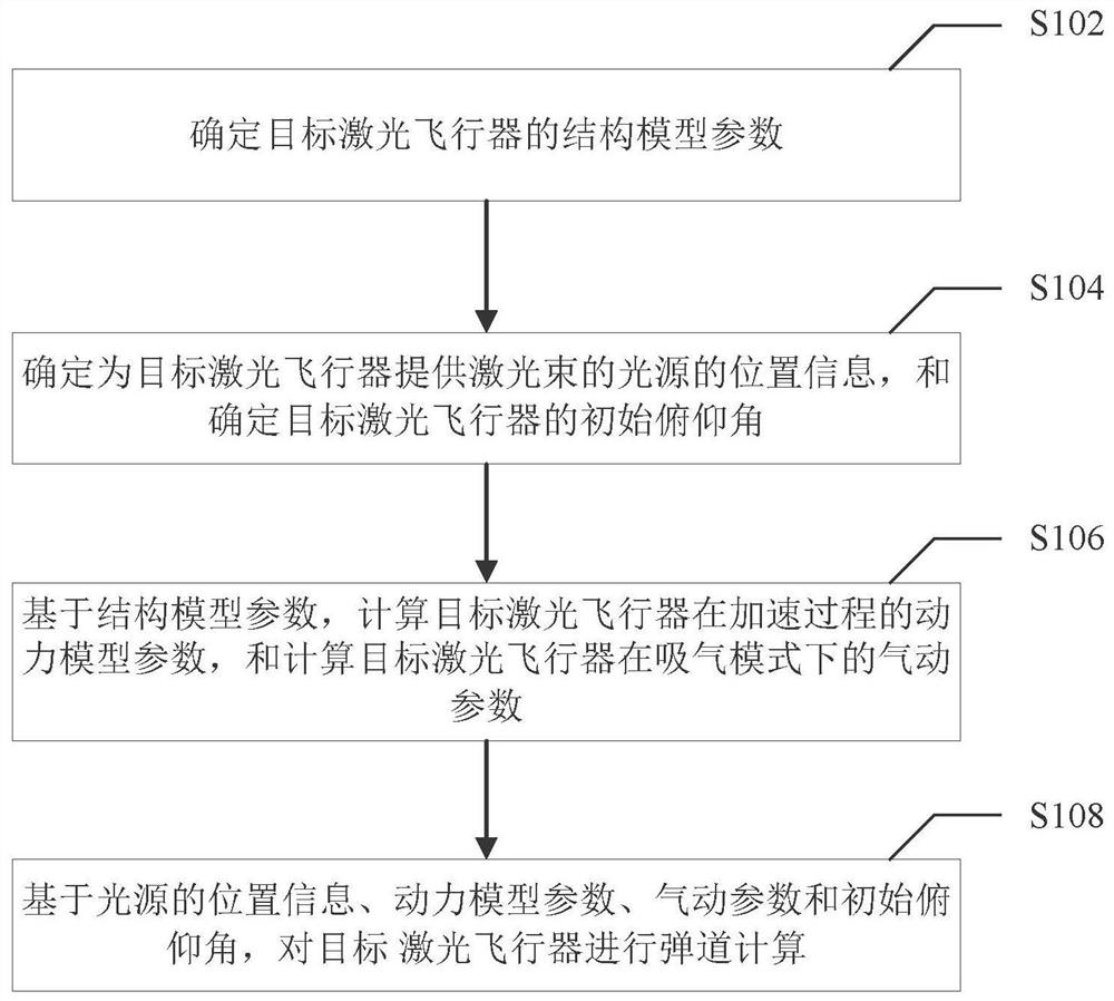
[0025] figure 1 It is a flowchart of a ballistic design method for a multi-light source laser aircraft provided according to an embodiment of the present invention. The method is applied to a target laser aircraft, wherein the target laser aircraft is a laser aircraft that provides laser beams for at least two light sources, and the target laser aircraft The model is Myrabo bareboat configuration. Such as figure 1 As shown, the method specifically includes the following steps:

[0026] Step S102, determining the structural model parameters of the target laser aircraft.

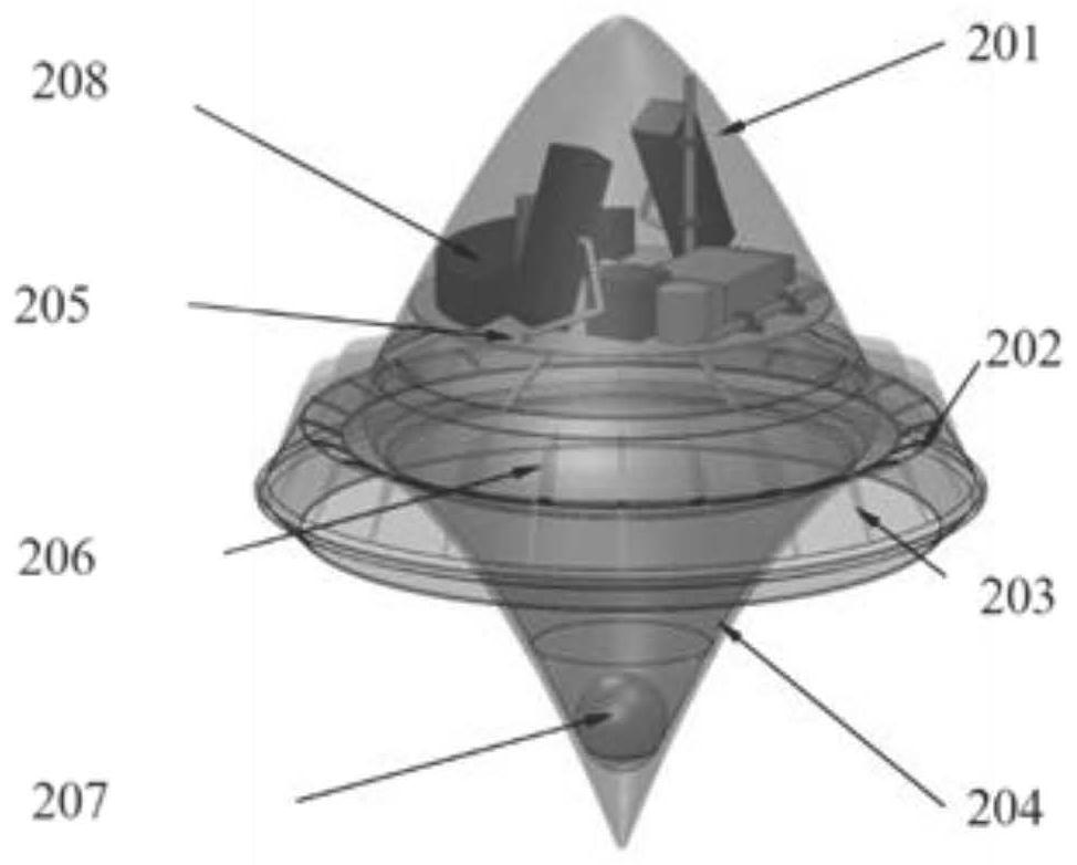
[0027] specific, figure 2 It is a schematic diagram of a Myrabo bareboat configuration provided according to an embodiment of the present invention. Such as figure 2 As shown, the external structure includes: a fairing 201, an annular sheath 202, an annular nozzle 203 and a parabolic reflector 204, and the direction of the generated thrust is along the axis of the bareboat. The internal structure inclu...

Embodiment 2

[0080] Figure 5 It is a schematic diagram of a multi-light source laser aircraft trajectory design system provided according to an embodiment of the present invention. The system is applied to a target laser aircraft. The target laser aircraft provides laser beams for at least two light sources. The model of the target laser aircraft is Myrabo bareboat configuration. Such as Figure 5 As shown, the system includes: a first determination module 10 , a second determination module 20 , a first calculation module 30 and a second calculation module 40 .

[0081] Specifically, the first determining module 10 is configured to determine structural model parameters of the target laser aircraft.

[0082] The second determination module 20 is configured to determine the position information of the light source that provides the laser beam for the target laser aircraft, and determine the initial pitch angle of the target laser aircraft.

[0083] The first calculation module 30 is conf...


PUM


Abstract

The invention provides a multi-light-source laser aircraft trajectory design method and system which are applied to a target laser aircraft. The target laser aircraft is a laser aircraft providing laser beams for at least two light sources, and the model of the target laser aircraft is a Myrabo light ship configuration. The method comprises the steps of determining structure model parameters of a target laser aircraft; determining position information of a light source for providing a laser beam for the target laser aircraft, and determining an initial pitch angle of the target laser aircraft; based on the structural model parameters, calculating dynamic model parameters of the target laser aircraft in an acceleration process, and calculating aerodynamic parameters of the target laser aircraft in an air suction mode; and performing trajectory calculation on the target laser aircraft based on the position information of the light source, the dynamic model parameters, the aerodynamic parameters and the initial pitch angle. The technical problem that in the prior art, a trajectory design method of a traditional chemical power carrier rocket is not suitable for trajectory design of a multi-light-source laser aircraft is solved.

Description

technical field [0001] The invention relates to the technical field of laser aircraft, in particular to a trajectory design method and system for a multi-light source laser aircraft. Background technique [0002] Laser propulsion is a new type of aircraft propulsion technology, which can use the laser beam emitted by the ground laser base station as the power source, so that the laser aircraft can generate thrust to complete the mission of satellite launch into orbit. [0003] The launch plan of laser aircraft involves multidisciplinary design such as structure, power, aerodynamics, and ballistics. There are few ballistic design methods related to domestic laser aircraft, most of which are single-ground laser station design, and most of the existing design methods are to design and integrate each discipline separately. The coupling variables between disciplines need to be iterated multiple times, and the time cost is relatively high Large, inconvenient for overall design op...

Claims


Application Information

Patent Timeline
IPC IPC(8): G05D1/10
CPCG05D1/101
Inventor 翁惠焱李志王鹏程徐维乐陈蓉朱浩
Owner BEIHANG UNIV
Why Eureka
Try Eureka