Buckle assembly and electronic device using the same

A technology for electronic devices and components, applied in the direction of electrical equipment shell/cabinet/drawer, connecting components, electrical components, etc., can solve the problems of E-ring falling off, screw teeth falling off, circuit board burning, etc., to achieve the effect of prolonging the service life

Pending Publication Date: 2021-09-03
PEGATRON
View PDF0 Cites 0 Cited by
  • Summary
  • Abstract
  • Description
  • Claims
  • Application Information

AI Technical Summary

Problems solved by technology

[0004] However, using metal E-rings actually has the following three risks of falling off:
[0005] 1. Due to the interference between the opening of the E-ring and the screw, if the operator engages the E-ring and the screw, it may deform the E-ring and cause the E-ring to fall off when the screw is unlocked later;
[0006] 2. If the thickness of the E-ring is the same as or smaller than the thread width of the screw, there is a chance that it will turn into the thread and cause it to fall off when the screw is unlocked. Although this point can be improved by increasing the thickness of the E-ring, it still cannot completely avoid;
[0007] 3. Because the screws of some models require electrical grounding, there will be a layer of conductive fiber cloth between the screw and the E-ring as a medium, but when the screw is unlocked, the conductive cloth may be involved in the screw and the E-ring. The gap between the E-rings causes the inner diameter of the E-rings to be stretched and fall off
[0008] The above three conditions may cause the E-ring to fall into the circuit board in the electronic device, causing a short circuit and burning the circuit board

Method used


Image

  • Buckle assembly and electronic device using the same
  • Buckle assembly and electronic device using the same
  • Buckle assembly and electronic device using the same

Examples


Embodiment Construction

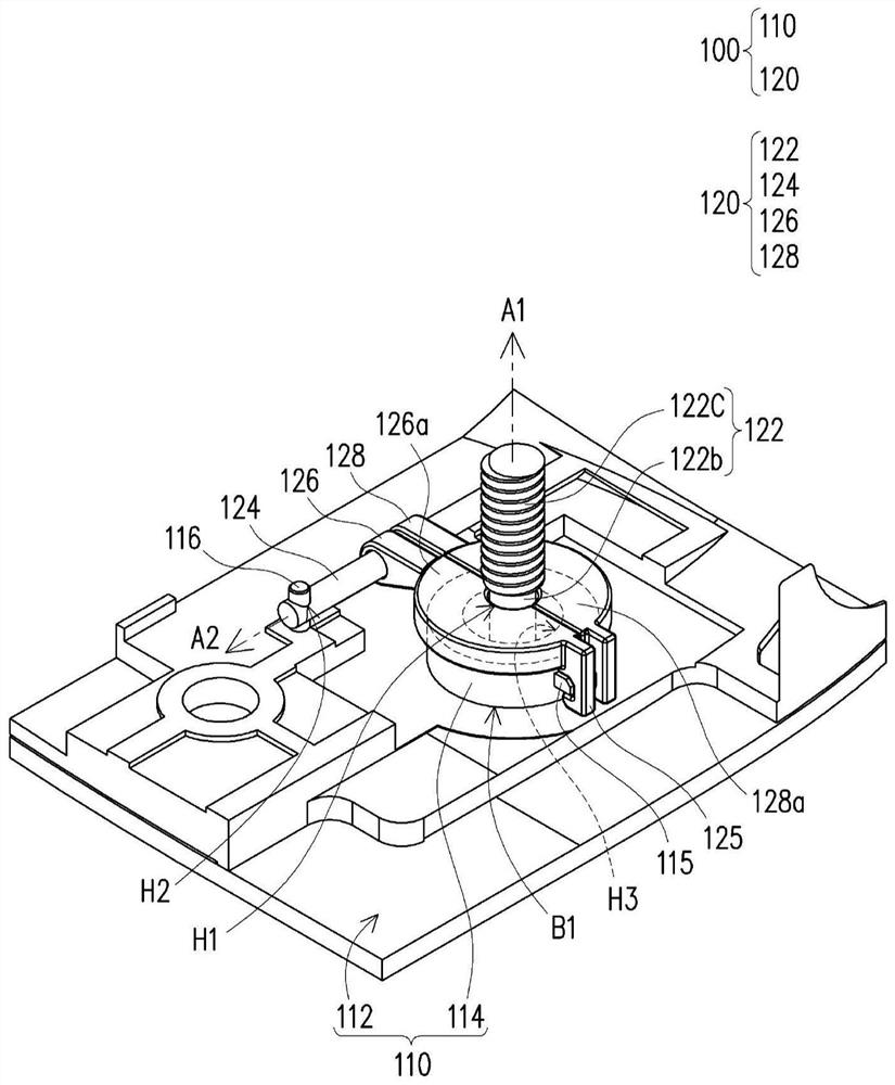
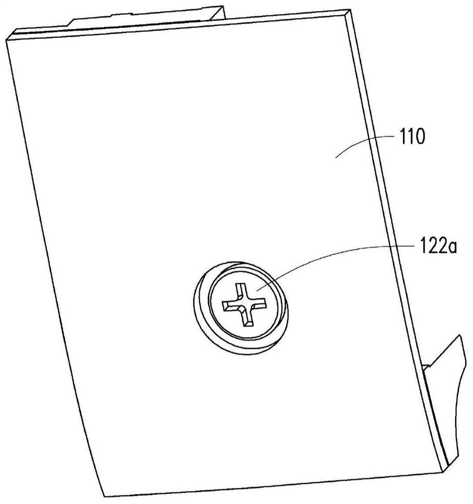
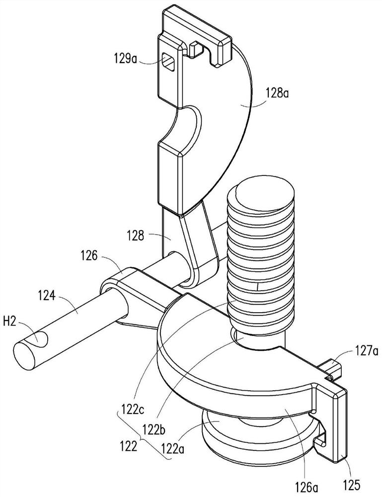
[0047] figure 1 is a partial schematic diagram of an electronic device according to an embodiment of the present invention, figure 2 for figure 1 Schematic diagrams of different viewing angles of the electronic device, while image 3 Schematic diagram of snap ring assembly to a fixed shaft for a snap-fit ​​assembly. Please also refer to figure 1 , figure 2 and image 3 , the electronic device 100 of this embodiment is a notebook computer, which includes a casing 110 and a buckle assembly 120 .

[0048] The casing 110 is the lower cover of the electronic device 100, which has an inner surface 112 and a hole B1, wherein the hole B1 has a side wall 114 and a first through hole H3, and the hole B1 faces from the inner surface 112 to the side of the casing 110. The interior stands out.

[0049] The buckle assembly 120 includes a lock 122 , a fixed shaft 124 and a pair of buckles 126 , 128 .

[0050] The lock piece 122 is used for assembling in the first through hole H3 of...


PUM


Abstract

A buckle assembly and an electronic device using the buckle assembly are provided. The buckle assembly is assembled in a housing of the electronic device. The housing has an inner surface and a column with a first through hole, wherein the column protrudes from the inner surface toward inside of the housing. The buckle assembly includes a fixing element, a shaft and a pair of retaining rings. The fixing element is assembled in the first through hole. The shaft is fixed in the housing. The retaining rings are pivoted to the shaft. Each of the retaining rings has an arc portion, and the retaining rings buckle each other and abut on the column. The arc portions are co-constructed to form a first hole communicating with the first through hole while the retaining rings buckle each other, and the fixing element is inserted in the first hole and column to be fixed in the housing.

Description

technical field [0001] The invention relates to a component and a device, in particular to a fastening component and an electronic device using the fastening component. Background technique [0002] The notebook computer is usually configured as a standard configuration to meet the requirements of customer replaceable units (CRU), so that the end user can disassemble the lower cover of the system side according to the requirement with only ordinary knowledge of mechanical disassembly and assembly. [0003] The known design usually utilizes the cooperation of the screw on the lower cover and the metal E-ring, and buckles the E-ring into the toothless area on the screw to fix the lower cover. [0004] However, using metal E-rings actually has the following three risks of falling off: [0005] 1. Due to the interference between the opening of the E-ring and the screw, if the operator engages the E-ring and the screw, it may deform the E-ring and cause the E-ring to fall off wh...

Claims


Application Information

Patent Timeline
Patent Type & Authority Applications(China)
IPC IPC(8): G06F1/16F16B21/02
CPCG06F1/1633F16B21/02G06F1/1658G06F1/1656G06F1/181H05K5/0221H05K5/0008F16B41/002
Inventor 胡耕祥林维隆杨庭豪谢承运
Owner PEGATRON
Why Eureka
Try Eureka