
A Finite Element Analysis Method for the Deformation Mode of Lattice Material

A material deformation and analysis method technology, applied in the direction of instruments, design optimization/simulation, electrical digital data processing, etc., can solve the problems of lack of quantitative and visual evaluation method of lattice material deformation mode, visual analysis, lack of guidance route, etc.

Active Publication Date: 2022-03-01
上海医钛科技有限公司 +1
View PDF1 Cites 0 Cited by
  • Summary
  • Abstract
  • Description
  • Claims
  • Application Information

AI Technical Summary

Problems solved by technology

Lattice materials have three deformation modes: stretching, bending and shearing deformation modes, where stretching deformation is the most efficient and bending deformation is less efficient
[0003] In the prior art, the Gibson-Ashby model and analytical model are mainly used to evaluate the deformation mode of lattice materials. The Gibson-Ashby model simply and generally divides lattice materials into tension-dominated and bending-dominated lattices according to the Maxwell equation. material, but ignores the bending and shearing deformation modes of stretch-dominated lattice materials and the tensile and shearing deformation modes of bending-dominant lattice materials, the Maxwell standard can only qualitatively determine which deformation mode the lattice material is , and it is a necessary and insufficient condition, which cannot realize visualization and quantitative analysis, and lacks a specific guiding route; the analytical model needs cumbersome and complicated mechanical derivation of the lattice material, and it is also impossible to determine which part and where in the structure of the lattice material. Visual analysis based on a deformation mode
At present, there is a lack of methods to quantitatively and visually evaluate the deformation mode of lattice materials, and the evaluation of deformation modes can guide the design of lattice materials dominated by tensile deformation modes, so as to obtain high-strength and high-rigidity lattice materials

Method used


Image

  • A Finite Element Analysis Method for the Deformation Mode of Lattice Material
  • A Finite Element Analysis Method for the Deformation Mode of Lattice Material
  • A Finite Element Analysis Method for the Deformation Mode of Lattice Material

Examples


Embodiment 1

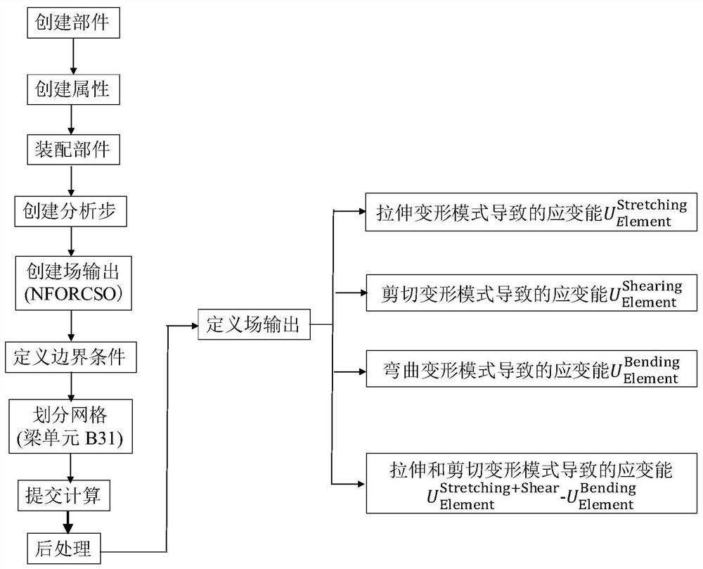
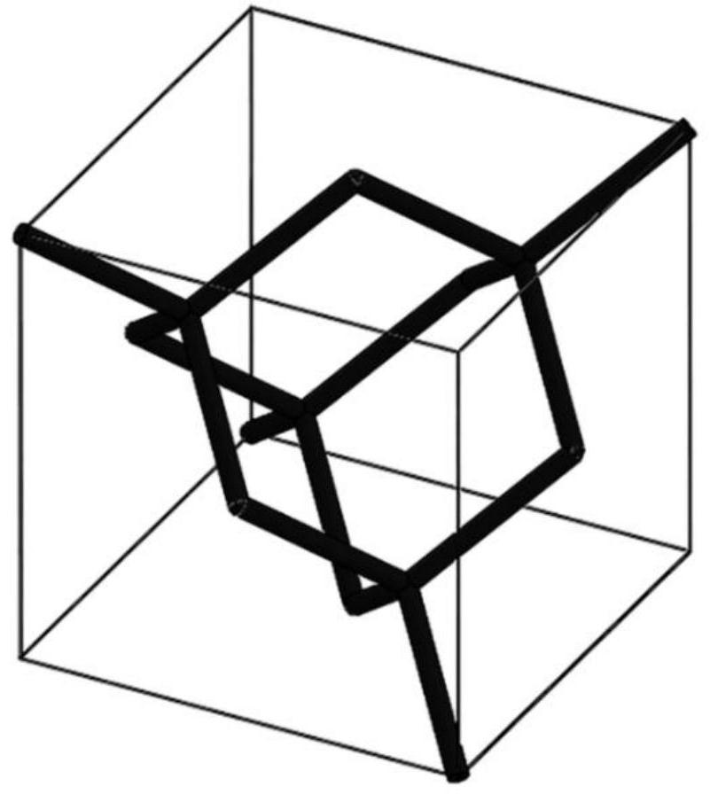
[0049] In this embodiment, the strain energy of the diamond model is quantitatively analyzed. In the diamond model ( figure 2 ) as an example, to obtain a lattice material whose slenderness is 10, adopt such as figure 1 The shown finite element analysis method obtains the strain energy distribution caused by the tensile deformation mode, bending deformation mode and shear deformation mode of the diamond lattice material as follows: image 3 As shown, the quantitative comparison of the strain energy caused by the above three deformation modes is shown in Table 1. It can be seen that the strain energy caused by the tensile deformation mode is much larger than that caused by the bending and shear deformation modes. When larger, diamond is a stretched lattice material.

[0050] Table 1: Strain energy due to different deformation modes in diamond as a function of slenderness

[0051]

[0052]

Embodiment 2

[0054]In this embodiment, a visual analysis of the strain energy of the diamond model as a function of the slenderness is performed. In the diamond model ( figure 2 ) as an example, analyze the strain energy caused by the tensile + shear deformation mode and the strain energy caused by only the bending deformation mode at different slenderness. When the slenderness is small, the strain energy caused by the tensile and shear deformation modes is greater than Strain energy due to bending deformation modes such as Figure 4 As shown, this visualization clearly rejects the Gibson-Ashby model's classification of diamond as a bend-dominated lattice material.

Embodiment 3

[0056] In this embodiment, the strain energy of the orthogonal dodecahedron model is quantitatively analyzed. In the orthogonal dodecahedron model ( Figure 5 ) as an example, to obtain a lattice material whose slenderness is 10, adopt such as figure 1 The shown finite element analysis method obtains the strain energy distribution caused by the tensile deformation mode, bending deformation mode and shear deformation mode of the orthogonal dodecahedral lattice material as follows: Figure 6 As shown, the quantitative comparison of the strain energy caused by the above three deformation modes is shown in Table 2. It can be seen that the strain energy caused by the tensile deformation mode is much larger than that caused by the bending and shear deformation modes. When larger, the orthogonal dodecahedron is a stretched lattice material.

[0057] Table 2: Variation of strain energy with slenderness due to different deformation modes in an orthorhombic dodecahedron

[0058]


PUM


Abstract

The invention discloses a finite element analysis method for a lattice material deformation mode, and belongs to the technical field of material mechanical performance analysis. The method includes establishing the finite element analysis model of the lattice material deformation mode, which sequentially includes creating parts, creating properties, assembling parts, creating analysis steps, creating field output variables, defining boundary conditions, dividing meshes, submitting calculations, and postprocessing Composed of sub-step units, a secondary finite element analysis is performed on the field output variable NFORCSO in ABAQUS / Standard mode, where the axial force, bending moment and shear force of the beam unit correspond to the tensile, bending and shear deformation modes, respectively, Obtain the strain energy caused by the three deformation modes of beam elements: tension, bending, and shear. The strain energy of the three-dimensional structure of the lattice material is the sum of the strain energies of all beam elements, which can realize the deformation of the lattice material during compression. Pattern quantification and visualization.

Description

technical field [0001] The invention belongs to the technical field of mechanical performance analysis of materials, and in particular relates to a finite element analysis method of a lattice material deformation mode. Background technique [0002] 3D printing technology has promoted the development of lattice material structure design and preparation technology. Since the successful preparation of lattice materials by 3D printing process in 2005, more and more complex lattice materials such as rods, plates and curved surfaces have emerged as the times require. pregnancy. Lattice materials have three deformation modes: stretching, bending, and shearing deformation modes, in which stretching deformation is the most efficient and bending deformation is less efficient. [0003] In the prior art, the Gibson-Ashby model and analytical model are mainly used to evaluate the deformation mode of lattice materials. The Gibson-Ashby model simply and generally divides lattice materials...

Claims


Application Information

Patent Timeline
Patent Type & Authority Patents(China)
IPC IPC(8): G06F30/23G06F119/14
CPCG06F30/23G06F2119/14
Inventor 钟豪章王淑侠莫翰轩顾剑锋
Owner 上海医钛科技有限公司
Learn More