An Intelligent Busway Conversion Mechanism

A technology of conversion mechanism and bus duct, applied in the field of bus duct, can solve the problems of easy inclination of alignment, lack of stability, reduced installation efficiency of staff, etc., and achieve the effect of increasing stability and stable design structure.

Active Publication Date: 2022-06-24
江苏华彤电气股份有限公司
View PDF5 Cites 0 Cited by
  • Summary
  • Abstract
  • Description
  • Claims
  • Application Information

AI Technical Summary

Problems solved by technology

[0003] A bus duct that is easy to install and has a plug-in conversion function (CN202021312741.0), discloses a bus duct that is easy to install and has a plug-in conversion function, which uses a bus duct shell, a connecting wire duct, a terminal box, a terminal body, Copper bar connection blocks, plug-in boxes, connectors, through holes, U-shaped rods, and clamping blocks are too simple to install and lack stability, which is not conducive to the convenience of on-site measurement and on-site busbar installation
[0004] In the prior art, most of the bus ducts are prone to inclination during the installation process, so the operation is more cumbersome, which will reduce the installation efficiency of the staff. Therefore, an intelligent bus duct conversion mechanism is needed to improve the installation efficiency of the bus duct. time stability

Method used


Image

  • An Intelligent Busway Conversion Mechanism
  • An Intelligent Busway Conversion Mechanism
  • An Intelligent Busway Conversion Mechanism

Examples


Embodiment 1

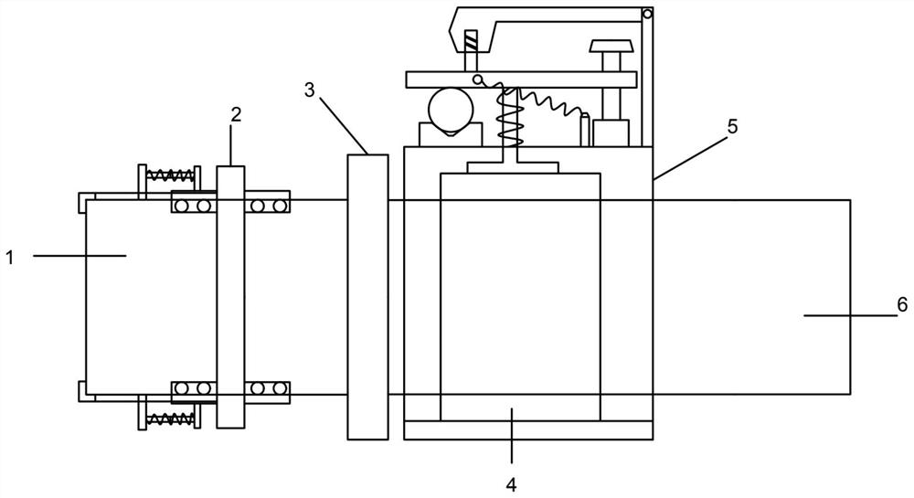
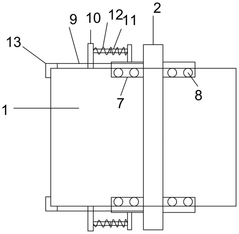
[0028] like Figure 1-5 As shown, an intelligent busway conversion mechanism includes a casting busbar 1, a side block 3 and a housing 5, a constraining frame 2 is sleeved on the casting busbar 1, and at least one side plate 7 is provided on both sides of the constraining frame 2, A first spring 8 is arranged on one side of the side plate 7, a casting bus 1 is arranged between the first springs 8, a pull rod 9 is slidably arranged on the top of the side plate 7, a mounting rod 10 is provided on the top of the pull rod 9, and one side of the mounting rod 10 is provided. There is a telescopic rod 11 , a second spring 12 is wound around the telescopic rod 11 , a top block is provided on one side of the telescopic rod 11 , and the top block is connected with the side plate 7 , and one end of the pull rod 9 is provided with an adapter block 13 .

[0029] The working principle of this embodiment:

[0030] Constraining frames 2 are sleeved on a plurality of pouring busbars 1. Side p...

Embodiment 2

[0032] like Figure 1-5 As shown, side blocks 3 are provided on both sides of the casting busbar 1, a transverse plate 24 is provided between the side blocks 3, a sliding rail 25 is provided on the top of the transverse plate 24, and at least one spring block 26 is provided on the sliding rail 25. There is a casting bus 1 between the blocks 26, a connecting block is provided on one side of the side block 3, and inserting rods 27 are provided on both sides of the bottom of the horizontal plate 24. A fifth spring 28 is provided between the connecting block and the fixing block 29; a side groove is provided on one side of the side block 3, and a plugging rod 31 is provided in the side groove, and a bending rod 30 is slid on the plugging rod 31. The bending rod 30 is connected with the horizontal plate 24 , and a sixth spring 32 is wound around the insertion rod 31 .

[0033] The working principle of this embodiment:

[0034] The side blocks 3 are arranged on both sides of the c...

Embodiment 3

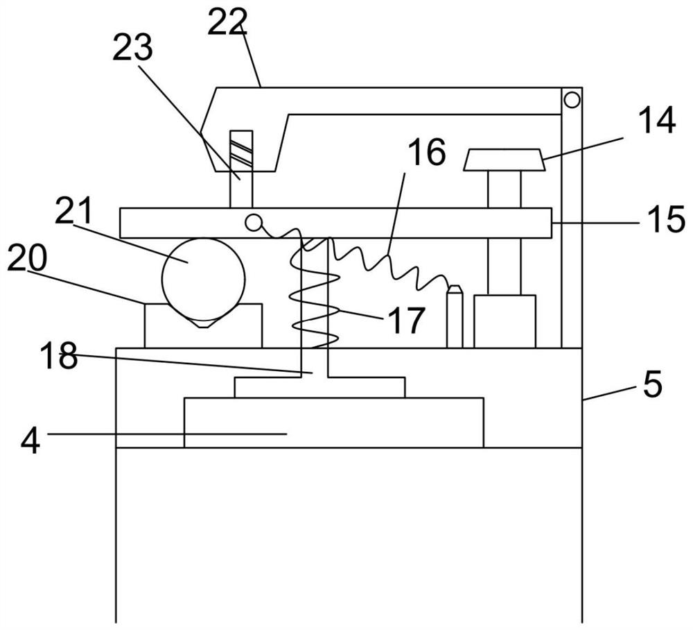
[0036] like Figure 1-5 As shown, a transition busbar 4 is sleeved on the casting bus 1, a casing 5 is sleeved on the transition busbar 4, a threaded rod 14 is provided on the top of the casing 5, and a lifting plate 15 is arranged on the threaded rod 14. The lifting plate 15 A pressure plate 18 is arranged at the bottom, a fourth spring 17 is arranged between the pressure plate 18 and the casing 5, a transition busbar 4 is arranged on the side of the pressure plate 18 passing through the casing 5, and a second spring 17 is arranged between the lifting plate 15 and the casing 5. Three springs 16;

[0037] A straight rod is provided on one side of the top of the housing 5 , a rotary pressure plate 22 is provided on the top of the straight rod, and a clamping piece 23 is provided on the top of the lifting plate 15 , and a rotary pressure plate 22 is provided between the clamping pieces 23 . The top of the housing 5 is provided with a cushion block 20 , the top of the cushion bl...


PUM


Abstract

The present invention provides an intelligent busway conversion mechanism, which relates to the technical field of bridges, and includes a pouring busbar, a side block and a housing. The pouring busbar is covered with a constraining frame, and at least one side plate is provided on both sides of the constraining frame. , a first spring is provided on one side of the side plate, the pouring bus bar is provided between the first springs, a pull rod is installed slidingly inside the top of the side plate, and a mounting rod is provided on the top of the pull rod, and the installation A telescopic rod is provided on one side of the rod, and a second spring is wound around the telescopic rod, and a top block is provided on one side of the telescopic rod, and the top block is connected with the side plate, and an adapter is provided at one end of the pull rod piece. The invention has reasonable structure and good application effect.

Description

technical field [0001] The invention belongs to the technical field of bus ducts, and in particular relates to an intelligent bus duct conversion mechanism. Background technique [0002] The bus duct is a closed metal device composed of copper and aluminum bus bars. It is used to distribute large power to each component of the decentralized system. It has been replaced more and more in indoor low-voltage power transmission trunk projects. Wire and Cable. [0003] A busbar (CN202021312741.0) that is easy to install and has a plug-in conversion function, discloses a busbar that is easy to install and has a plug-in conversion function, which adopts a busbar groove shell, a connecting wire groove, a terminal box, a terminal body, Copper bar connection blocks, plug boxes, connectors, through holes, U-shaped rods, and clamping blocks are too simple to install and lack stability, which is not conducive to on-site measurement and the convenience of on-site busbar installation. [...

Claims


Application Information

Patent Timeline
Patent Type & Authority Patents(China)
IPC IPC(8): H02G5/06
CPCH02G5/06
Inventor 赵义平赵晨
Owner 江苏华彤电气股份有限公司
Why Eureka
Try Eureka