Electric blower

An electric blower and fan technology, which is applied to machines/engines, liquid fuel engines, mechanical equipment, etc., can solve problems such as the decrease in blowing efficiency and the inability to fully ensure the airtightness of the fan casing and the fan casing spacer.

Inactive Publication Date: 2021-09-03
PANASONIC INTELLECTUAL PROPERTY MANAGEMENT CO LTD
View PDF5 Cites 0 Cited by
  • Summary
  • Abstract
  • Description
  • Claims
  • Application Information

AI Technical Summary

Problems solved by technology

However, in conventional electric fans, the airtightness between the fan case and the fan case spacer cannot be sufficiently ensured, resulting in a decrease in blowing efficiency.

Method used


Image

  • Electric blower
  • Electric blower
  • Electric blower

Examples


Embodiment approach

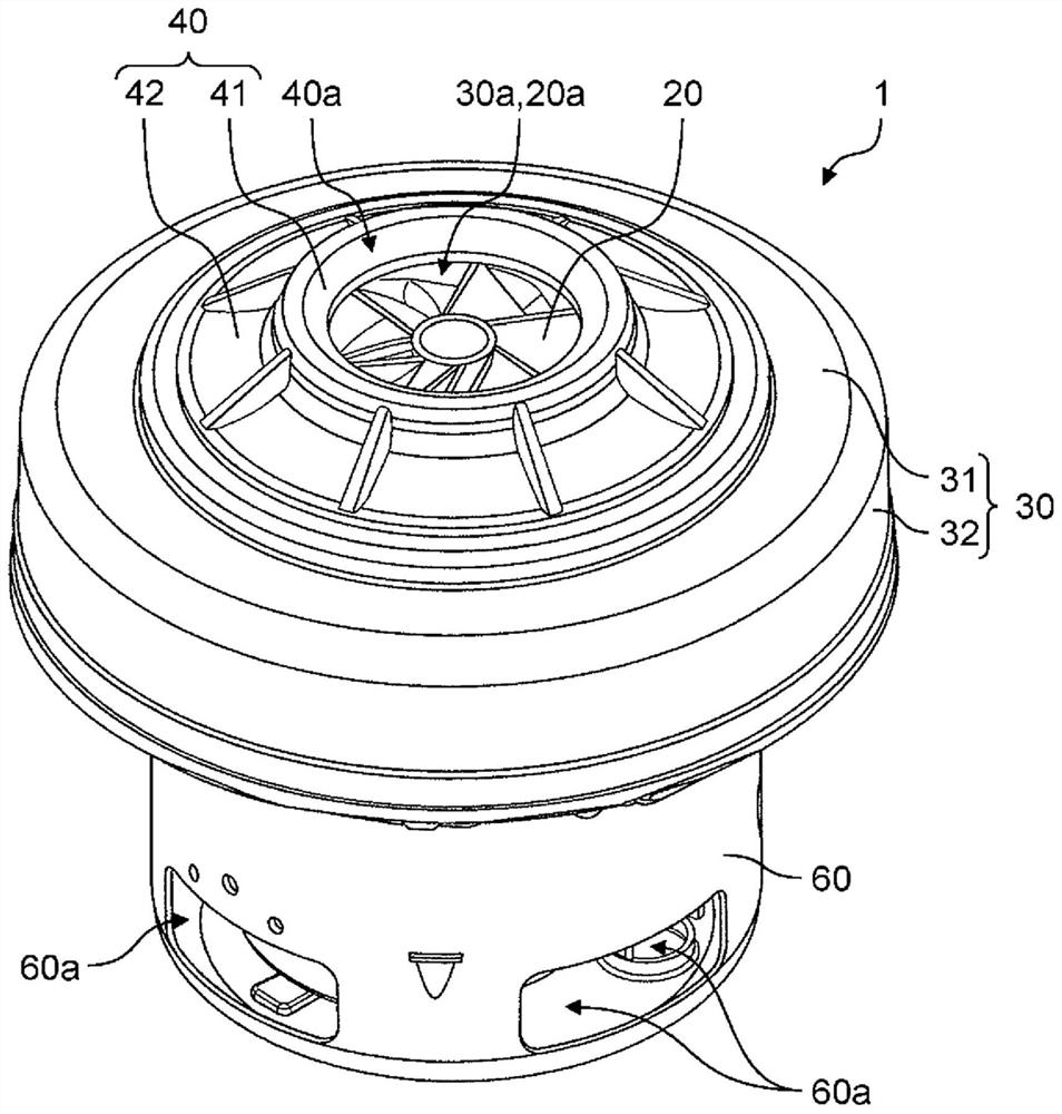
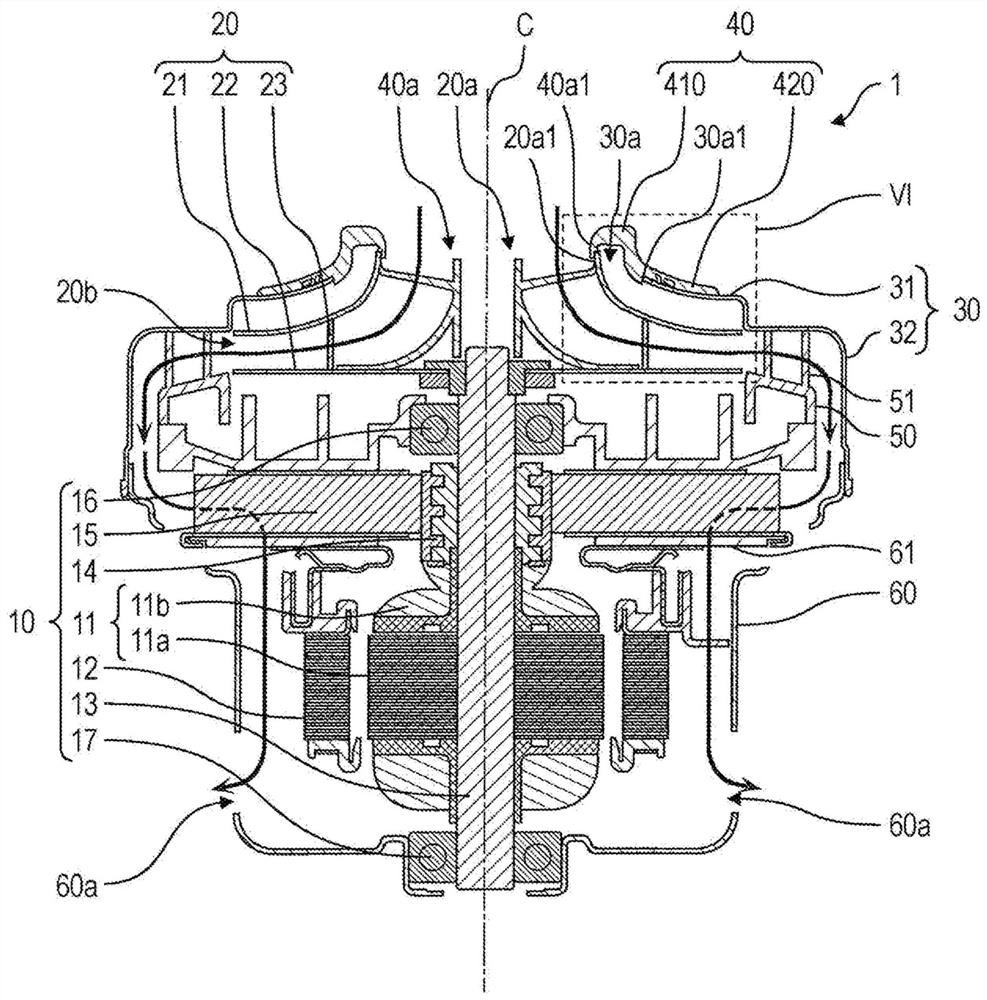
[0023] First, use figure 1 and figure 2 , and the overall structure of the electric fan 1 according to the embodiment will be described. figure 1 It is an external perspective view of the electric blower 1 of embodiment. figure 2 It is a cross-sectional view of electric blower 1 according to the embodiment. figure 2 A cross section of the electric fan 1 taken along a plane passing through the axis C of the rotating shaft 13 is shown. In addition, in figure 2 In , only the line graphs that appear in the section are shown. figure 2 The shown bold arrows indicate the flow of air sucked into the electric blower 1 .

[0024] In the description below, for convenience, the direction in which the axis C extends is referred to as the vertical direction. Specifically, in figure 2 In the direction in which the axis C extends, the output shaft side where the centrifugal fan 20 is located is set to the upper side with respect to the rotor 11, and the output shaft where the sec...


PUM


Abstract

An electric blower (1) comprises: a rotor (11) having a rotary shaft (13); a centrifugal fan (20) which is attached to the rotary shaft and has a first opening (20a); a fan case (30) which covers the centrifugal fan and has a second opening (30a), an opening end thereof being located outward of an opening end of the first opening; and a fan case spacer (40) which is attached to the fan case and has a third opening (40a) which communicates with the first opening. The fan case spacer (40) has: a spacer part (410) which closes off a space between the opening end of the first opening and the opening end of the second opening; and a cover part (420) which extends outward from the opening end of the second opening and covers an outer surface of the fan case. The cover part (420) has a ring-shaped protrusion (421) which protrudes toward the outer surface of the fan case and surrounds the second opening. The protrusion (421) is located between the opening end of the second opening and a tip part (422) of the cover part, and contacts the outer surface of the fan case.

Description

technical field [0001] The present disclosure relates to an electric fan. Background technique [0002] Electric fans are used in various electrical equipment such as electric vacuum cleaners. The electric blower installed in the electric vacuum cleaner adopts a centrifugal fan capable of obtaining high suction pressure as a rotating fan. The centrifugal fan is attached to the rotating shaft of the motor and rotates at high speed to generate desired wind pressure. [0003] An electric fan using a centrifugal fan includes, for example, a motor, a centrifugal fan attached to a rotating shaft of the motor, a fan case covering the centrifugal fan, and a fan case spacer attached to the fan case (for example, refer to Patent Document 1). [0004] In order to improve the blowing efficiency of the electric fan, it is important to ensure airtightness between the fan case and the fan case spacer. However, in conventional electric fans, the airtightness between the fan case and the ...

Claims


Application Information

Patent Timeline
Patent Type & Authority Applications(China)
IPC IPC(8): F04D29/16F04D29/44
CPCF04D29/4206F04D29/624F04D29/162F04D17/165F04D29/4253F04D29/4213F04D29/023F04D29/4226
Inventor 山口明
Owner PANASONIC INTELLECTUAL PROPERTY MANAGEMENT CO LTD
Why Eureka
Try Eureka