Efficient energy-saving centrifugal blower

An energy-saving, centrifugal technology, used in mechanical equipment, non-variable-capacity pumps, machines/engines, etc., can solve problems such as high failure rate, reduced useful power of blowers, complex impeller structure, etc., to achieve stable gas flow rate and pressure. , The use of safe and reliable, improve the effect of blasting efficiency

Active Publication Date: 2019-12-03
德耐尔能源装备有限公司
View PDF10 Cites 0 Cited by
  • Summary
  • Abstract
  • Description
  • Claims
  • Application Information

AI Technical Summary

Problems solved by technology

Although the invention can realize two-way air intake, the structure of the impeller is complex, there are too many parts, and the failure rate is high
[0007] In addition, although the centrifugal blower has a wide range of uses, the energy consumption of various traditional centrifugal blowers is generally too large. Most of the centrifugal blower impeller designs are not reasonable, and some of the centrifugal blower outlets are not well designed. , resulting in a reduction in the useful power used by the blower as a whole, wasting energy

Method used


Image

  • Efficient energy-saving centrifugal blower
  • Efficient energy-saving centrifugal blower
  • Efficient energy-saving centrifugal blower

Examples


Embodiment 1

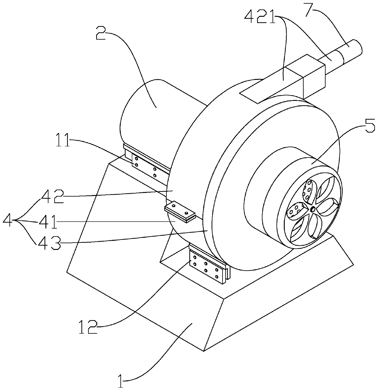
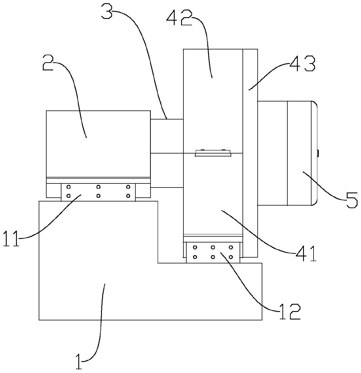
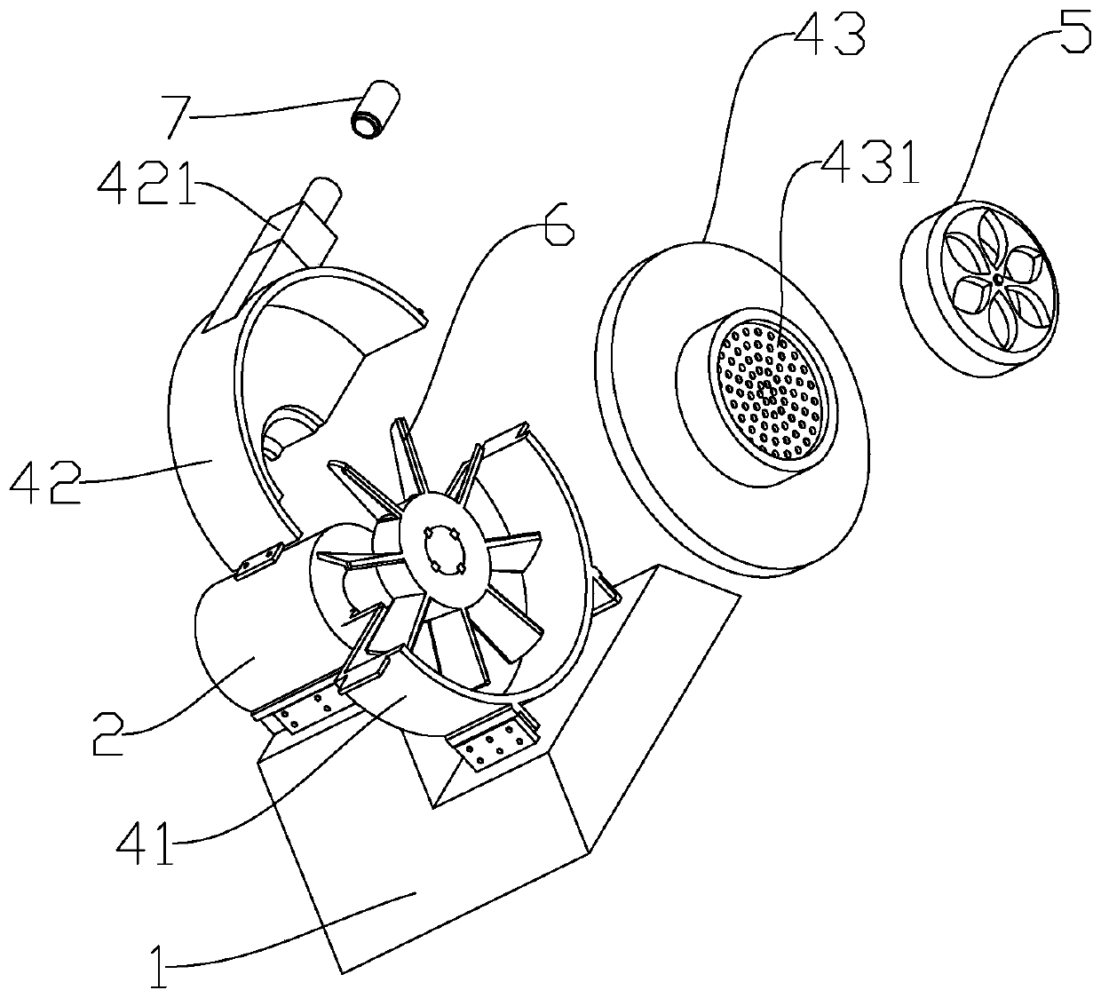
[0041] Such as Figures 1 to 5 As shown, a high-efficiency and energy-saving centrifugal blower includes a base 1, on which a motor 2 is arranged; connected; the casing 4 includes a lower casing 41, an upper casing 42 and a side cover 43; after the lower casing 41 is connected with the upper casing 42, the side cover 43 is detachably and fixedly connected to the lower casing On the side of the casing 41 and the upper casing 42 away from the side of the motor 2, the sealing sleeve 3 is detachably and fixedly connected to the side of the lower casing 41 and the upper casing 42 close to the side of the motor 2 Above; the impeller 6 includes a blade 61, the blade 61 is a curved surface, and its radius of curvature is 60-80; the blade 61 is also provided with a wind gathering frill 611 near the side cover 43; The distance between the wind frill 611 and the blade 61 is 8-15 mm, and the distance gradually decreases along the direction close to the center of the blade 61; the upper c...

Embodiment 2

[0043] Such as Figures 1 to 5 As shown, a high-efficiency energy-saving centrifugal blower, including

[0044] A machine base 1, the said machine base 1 is provided with a motor 2;

[0045] The output end of the motor 2 passes through the sealing sleeve 3 and is connected with the impeller 6 in the casing 4;

[0046] The casing 4 includes a lower casing 41, an upper casing 42 and a side cover 43; the lower casing 41 is connected to the upper casing 42 (welding, or other detachable fixed connection methods, such as screw connections; necessary At present, rubber gaskets are arranged on the contact surface of the lower casing 41 and the upper casing 42 to improve the sealing performance, and the same or similar methods can be used for other joints in the same way) After the sealing performance is improved, the side cover 43 is detachable and fixed Connected to the side of the lower casing 41 and the upper casing 42 away from the motor 2, the sealing sleeve 3 is detachably and...


PUM

PropertyMeasurementUnit
Thicknessaaaaaaaaaa

Abstract

The invention discloses an efficient energy-saving centrifugal blower which comprises a machine base, and a motor is arranged on the machine base; the output end of the motor penetrates through the sealing sleeve and is connected with an impeller in the machine shell. The machine shell comprises a lower machine shell body, an upper machine shell body and a side cover. The impeller comprises blades, the blades are the shape of curved surfaces, and the curvature radius of each blade is 60-80; wind gathering folded edges are further arranged on the blades; the distance between each wind gatheringfolded edge and the corresponding blade is 8-15mm, and the distance is gradually reduced along the direction close to the center of the blades; an air outlet is formed in the upper machine shell body, the size of the cross section in the air outlet is reduced in a two-step mode, and the air outlet is sequentially divided into a first pressurizing area, a pressure stabilizing area and a second pressurizing area in the air flowing direction. According to the efficient energy-saving centrifugal air blower, the impeller is reasonable in design and good in air buckling effect, the air blowing efficiency is improved, energy consumption is reduced, the air outlet of the upper machine shell body is reasonable in design, air exhausting is smoother, the overall working efficiency is improved, and therefore the purposes of high efficiency and energy saving are achieved.

Description

technical field [0001] The invention relates to the field of blowers, in particular to a high-efficiency and energy-saving centrifugal blower. Background technique [0002] The centrifugal blower is a machine that relies on the input mechanical energy to increase the gas pressure and discharge the gas. It is a driven fluid machine. Centrifugal blowers are widely used in ventilation, dust removal and cooling of factories, mines, tunnels, cooling towers, vehicles, ships and buildings; ventilation and induction of boilers and industrial furnaces; cooling in air conditioning equipment and household appliances and ventilation; drying and selection of grain; wind tunnel wind source and inflation and propulsion of hovercraft, etc. [0003] The patent application number is CN201020139604.1, which provides a double-impeller rotor. The rotor includes two impellers, a balance plate, a shaft sleeve, two stop washers, and two round nuts; the blades of the impeller are two sections Arc ...

Claims


Application Information

Patent Timeline
IPC IPC(8): F04D25/06F04D29/28F04D29/30F04D29/42F04D29/70F04D29/66
CPCF04D25/0606F04D29/281F04D29/30F04D29/4226F04D29/663F04D29/701
Inventor 盛昌国
Owner 德耐尔能源装备有限公司
Why Eureka
Try Eureka