
Dehumidification device convenient to move for high-pressure chamber

A high-pressure chamber and dehumidifier technology, which is applied to the separation of dispersed particles, chemical instruments and methods, separation methods, etc., can solve the problems of limited dehumidification range of intake air, large volume of dehumidifiers, and inconvenience for users.

Pending Publication Date: 2021-09-07
张家港市天源电气有限公司
View PDF0 Cites 0 Cited by
  • Summary
  • Abstract
  • Description
  • Claims
  • Application Information

AI Technical Summary

Problems solved by technology

[0003] The high-voltage room generally uses a cable trench to enter the line, which makes the air humidity in the high-voltage room very high. The humid air will enter the switch cabinet and condense into water droplets in the switch cabinet. The water droplets will corrode the monitoring and control instruments on the switch cabinet. In severe cases, it will also lead to short circuit, which poses a serious threat to power transmission safety
[0004] Existing dehumidifiers generally can only dehumidify a certain range around themselves, and the air inlet is not equipped with a telescopic stretching mechanism, the dehumidification range of the air inlet is limited, and the dehumidification efficiency is low. At the same time, the dehumidifier is too large and generally fixed In the high-pressure chamber, it cannot be moved, which is very inconvenient for users to use

Method used


Image

  • Dehumidification device convenient to move for high-pressure chamber
  • Dehumidification device convenient to move for high-pressure chamber
  • Dehumidification device convenient to move for high-pressure chamber

Examples


Embodiment Construction

[0030] The following will clearly and completely describe the technical solutions in the embodiments of the present invention with reference to the accompanying drawings in the embodiments of the present invention. Obviously, the described embodiments are only some, not all, embodiments of the present invention. Based on the embodiments of the present invention, all other embodiments obtained by persons of ordinary skill in the art without making creative efforts belong to the protection scope of the present invention.

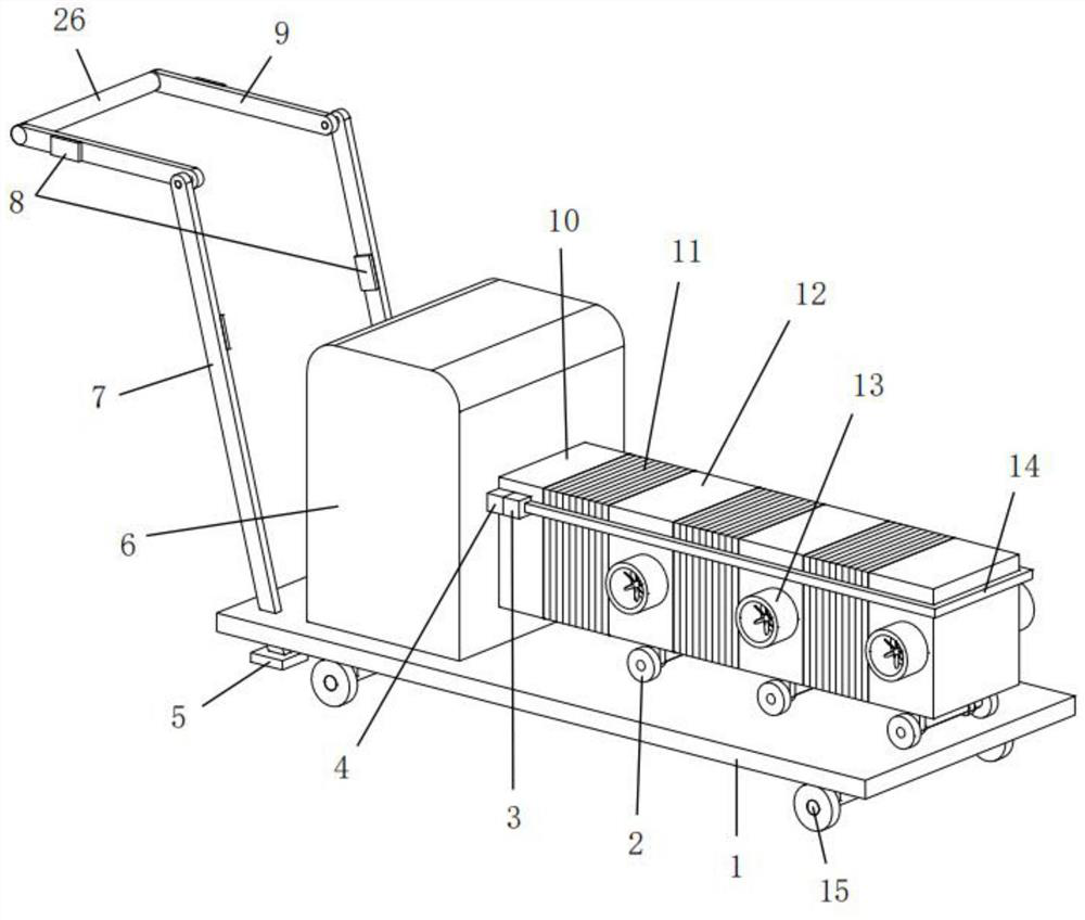
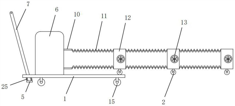
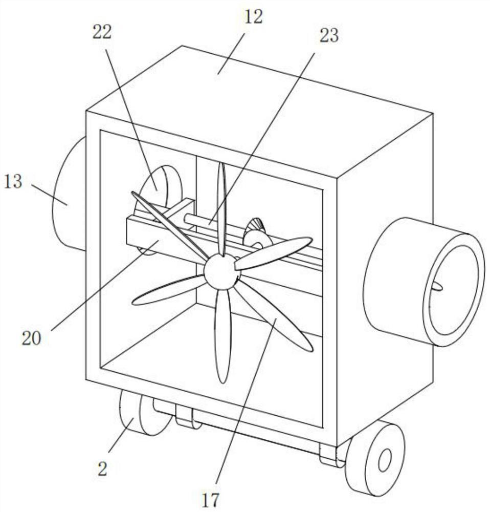
[0031] see Figure 1~4 , in an embodiment of the present invention, a dehumidification device for a high-pressure chamber that is easy to move includes a support plate 1, a moving mechanism, an air intake mechanism, and an acceleration mechanism. The lower end of the support plate 1 is fixedly installed with a second The moving wheel 15, the upper end of the support plate 1 is fixedly installed with a dehumidifier body 6 for dehumidification, and an air inlet ...


PUM


Abstract

The invention discloses a dehumidification device convenient to move for a high-pressure chamber. The dehumidification device comprises a supporting plate, a moving mechanism, an air inlet mechanism and an acceleration mechanism. A dehumidifier body is fixedly installed at the upper end of the supporting plate, and an air inlet is formed in the side wall of the dehumidifier body. As a swing rod and a push rod are in rotating connection, the supporting plate can be moved by workers with different heights, meanwhile, when the supporting plate does not move, the brake plate is tightly attached to the ground, the supporting plate is prevented from moving, the air inlet frame is distributed in the whole high-pressure chamber through the flexibility of the telescopic cylinder, the air inlet area is increased, and then the dehumidification efficiency of the high-pressure chamber is improved; the force of air entering the air inlet pipe is used for driving the first fan blade to rotate, the first fan blade drives the second fan blade to rotate, the second fan blade accelerates air flow in the telescopic cylinder, and therefore the negative pressure in the side, away from the air inlet, of the telescopic cylinder is increased, and the air inlet efficiency of the side, away from the air inlet, of the air inlet pipe is improved.

Description

technical field [0001] The invention relates to the technical field of high pressure chamber dehumidification, in particular to a mobile dehumidification device for a high pressure chamber. Background technique [0002] The power distribution room refers to an indoor power distribution place with low-voltage loads. Facilities for equipment with a voltage level of 10kV and below are divided into high-voltage power distribution rooms and low-voltage power distribution rooms. The high-voltage power distribution room generally refers to the 6kV-10kV high-voltage switch room; the low-voltage power distribution room generally refers to the 400V power distribution room for 10kV or 35kV station transformers. [0003] The high-voltage room generally uses a cable trench to enter the line, which makes the air humidity in the high-voltage room very high. The humid air will enter the switch cabinet and condense into water droplets in the switch cabinet. The water droplets will corrode t...

Claims


Application Information

Patent Timeline
Patent Type & Authority Applications(China)
IPC IPC(8): B01D53/26
CPCB01D53/26
Inventor 李志刚金利忠
Owner 张家港市天源电气有限公司
Learn More