
A bionic hand mechanism and a robot using the bionic hand mechanism

A bionic hand and palm technology, applied in the field of bionic hand mechanisms, can solve the problems of impossibility of fine movements, weak grip, and inflexible use

Active Publication Date: 2022-06-17
CHANGZHOU JINGANG NETWORK TECH
View PDF8 Cites 0 Cited by
  • Summary
  • Abstract
  • Description
  • Claims
  • Application Information

AI Technical Summary

Problems solved by technology

[0003] The patent application with the publication number CN109227586A and the publication date of 2019.01.18 discloses a bionic hand with a pull wire. This bionic hand includes a palm assembly mechanism and a finger mechanism. Each finger mechanism is equipped with a support block and a pull wire. The pull wires respectively pass through the support block and are connected to the stepping motor to realize the control of the finger mechanism. In this bionic hand, the pull wire passes through the pull wire tube and the support block in turn. The number of degrees of freedom of the joints of the simulated human hand is insufficient, and each finger lacks the root swing. Degree of freedom, so it is not flexible enough to use, and many fine movements cannot be realized
In addition, this bionic hand uses a cable tube to simulate bones, and the support block and the tube are connected by a cable. Once the cable breaks, the support block and the tube will be separated, so the overall grip of this bionic is relatively small.

Method used


Image

  • A bionic hand mechanism and a robot using the bionic hand mechanism
  • A bionic hand mechanism and a robot using the bionic hand mechanism
  • A bionic hand mechanism and a robot using the bionic hand mechanism

Examples


Embodiment Construction

[0039] The present invention will be described in detail below with reference to the accompanying drawings and specific embodiments.

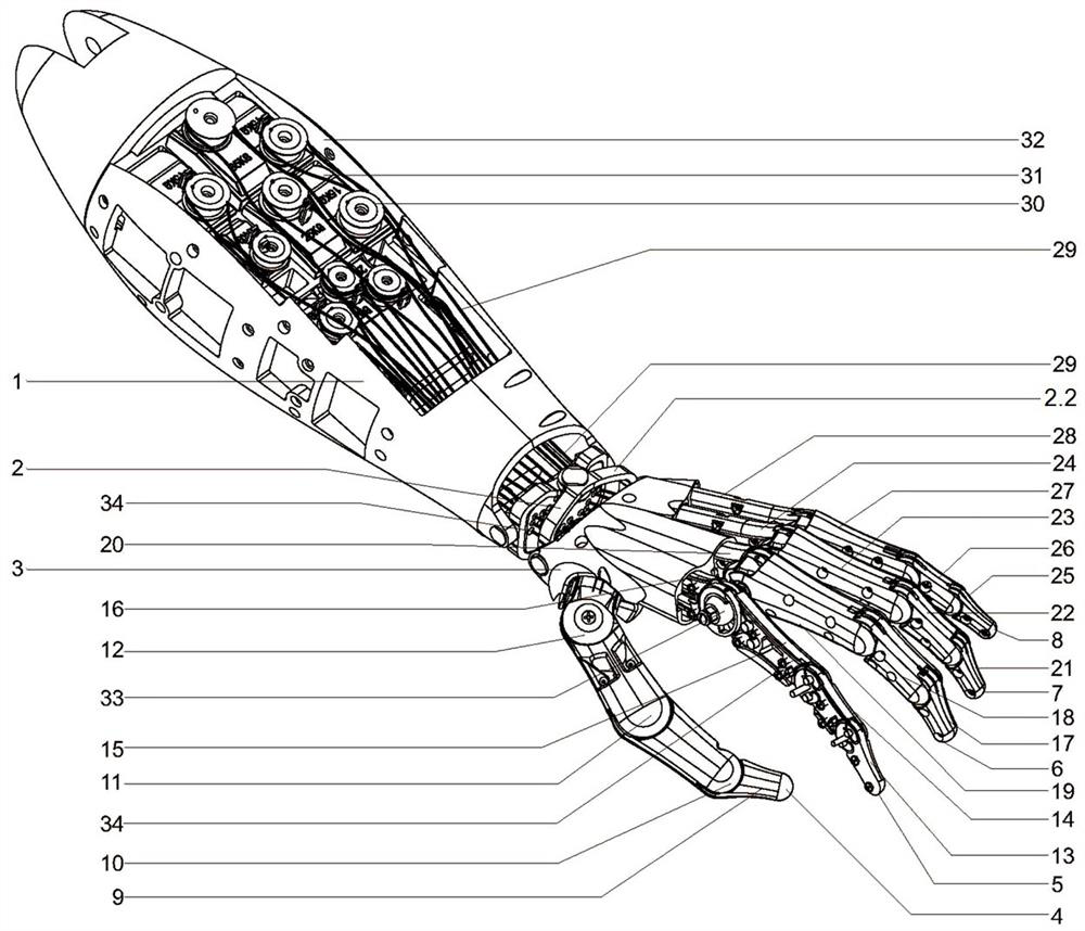
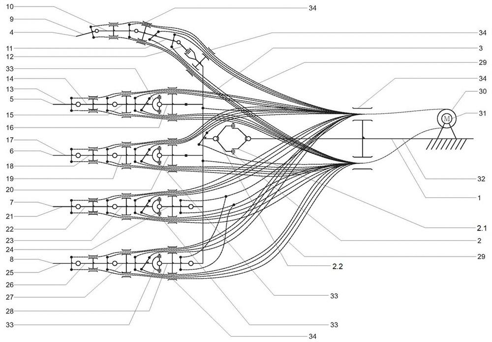
[0040] The structure of an embodiment of the bionic hand mechanism of the present invention is as follows: figure 1 As shown, the bionic hand mechanism of this embodiment includes an arm assembly 1, a palm assembly 3 and five finger assemblies, and the five finger assemblies are the thumb 4, the index finger 5, the middle finger 6, the ring finger 7 and the little finger 8 respectively. There is a motor 31 and a winch 30 that rotates under the drive of the motor 31. The pulling wire 29 is wound on the winch 30. The arm assembly 1 includes a support frame located inside and a casing 32 located outside. The motor 31 and the winch are wound. The wheels 30 are arranged on the support frame.

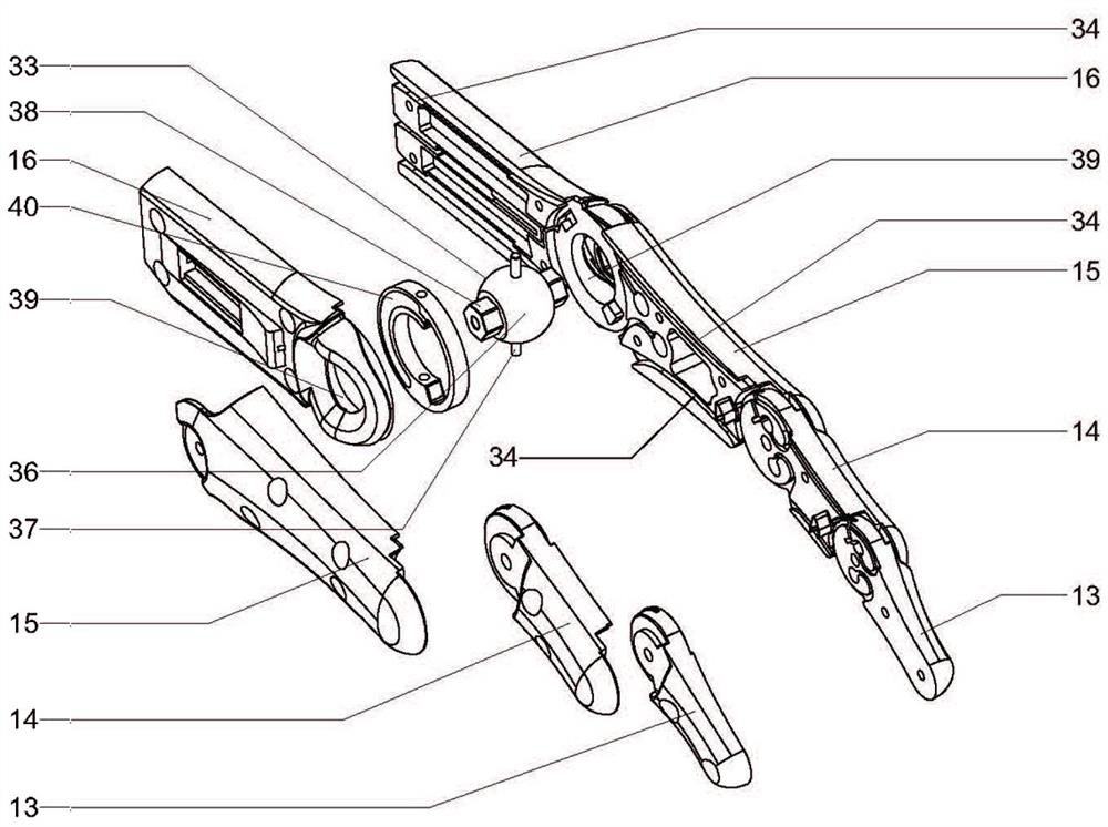
[0041] Each finger assembly includes four joints, and the four joints of each finger assembly are the first, second, third, and fourth sections, respectively...


PUM


Abstract

The invention discloses a bionic hand mechanism, which includes an arm assembly, a palm assembly and five finger assemblies. The arm assembly is provided with a motor and a winch wheel driven by the motor. A pull wire is wound on the winch wheel. Each finger assembly is Including four joints, the four joints of each finger assembly are the first joint, second joint, third joint, and fourth joint. The finger assembly has a total of 21 degrees of freedom. The third joint of the index finger and the middle finger The third joint of the ring finger, the third joint of the ring finger, and the third joint of the little finger realize the rotation in two directions respectively through the two-degree-of-freedom ball shaft. The degree of freedom is connected by the ball shaft, and the motor that controls the pull wire is located on the arm, which does not occupy the space in the finger and palm assembly, so the structural design is more compact, the finger movement is highly flexible, and can completely imitate the movement of the human hand, while meeting the demand for greater grip , can reach normal manpower.

Description

technical field [0001] The invention relates to a bionic hand mechanism and a robot using the bionic hand mechanism, belonging to the technical field of robotics. Background technique [0002] The field of intelligent bionic hand technology at home and abroad has been initiated since the 1990s. Up to now, EEG signal control, simple pinching and grasping, basic tactile feedback, etc. have been realized, but more complex and delicate bionic movements have not yet been realized. The medical field has obtained a certain range of applications, but it still cannot allow the recipient to obtain the ability closer to the real hand. Most of the existing bionic manipulators at home and abroad use ultra-miniature steering gear and push rod-type micro-motor devices, which are usually installed in the palm assembly, so only micro-motors with small size and low power can be used. In addition, the transmission structure of the finger joints is complex, so the mechanical efficiency of this...

Claims


Application Information

Patent Timeline
Patent Type & Authority Patents(China)
IPC IPC(8): B25J15/00B25J15/02B25J17/02
CPCB25J15/0009B25J15/02B25J17/0258
Inventor 王鹏勃甘贤俊高胜杰
Owner CHANGZHOU JINGANG NETWORK TECH
Learn More