Carrier rocket sublevel recovery landing system and method

A carrier rocket and landing system technology, which is applied in the field of carrier rocket sub-stage recovery and landing system, can solve problems such as the loss of carrier rocket carrying capacity, and achieve the effects of avoiding the decline of carrying capacity, improving carrying capacity, and reducing mass

Pending Publication Date: 2021-09-07
BEIJING INTERSTELLAR GLORY TECH LLC +1
View PDF0 Cites 10 Cited by
  • Summary
  • Abstract
  • Description
  • Claims
  • Application Information

AI Technical Summary

Problems solved by technology

[0011] Therefore, the technical problem to be solved by the present invention is to overcome the defect that the launch vehicle sub-stage recovery and landing system in the prior art caus...

Method used


Image

  • Carrier rocket sublevel recovery landing system and method
  • Carrier rocket sublevel recovery landing system and method
  • Carrier rocket sublevel recovery landing system and method

Examples


Embodiment 1

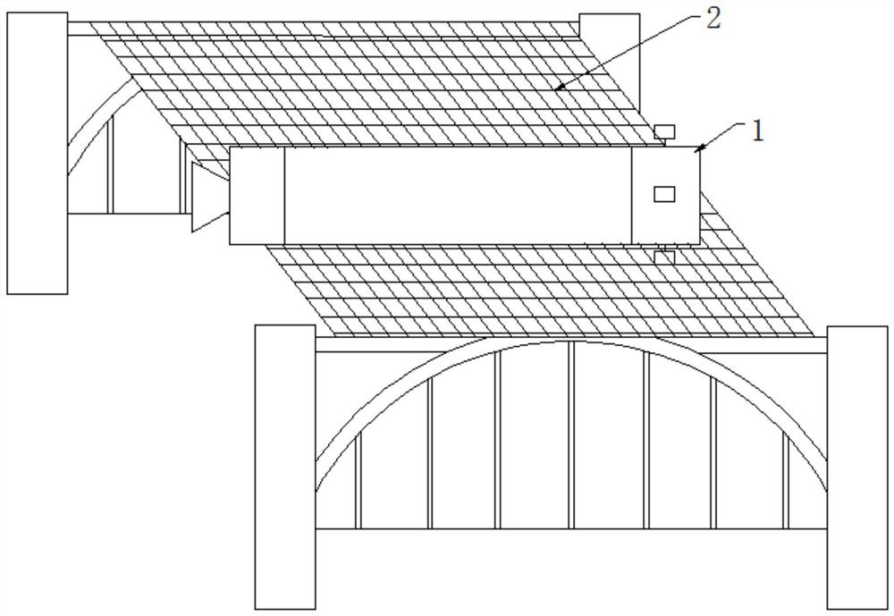
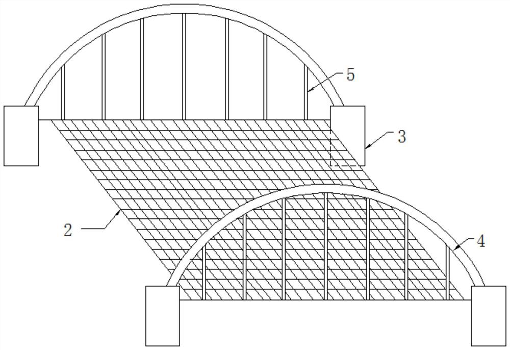
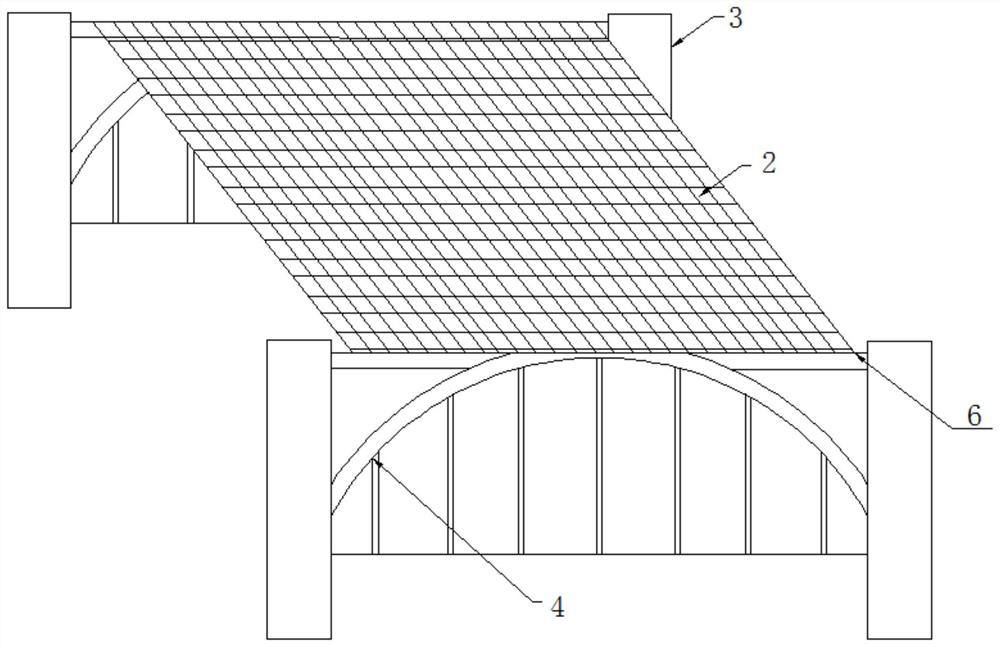
[0052] The main problem of vertical landing recovery technology is that the loss of launch vehicle capability is relatively large. In terms of payload loss, in order to achieve reusability and manned safety, the payload of the space shuttle has been reduced by almost 50%; if the Angara series uses the Baikal reusable sub-stage, its payload will be larger than that of the full one Sexual use decreased by 43%. It can be seen that in order to achieve reusability, the loss of rocket payload carrying capacity is quite staggering.

[0053] For sub-stages with landing legs installed, the reason for the loss of carrying capacity is the high mass of the landing legs, with at least four support frames. In the launch ascent section, the support is a burden, completely useless, and adds additional aerodynamic resistance; in the return section, the landing legs are opened and locked, and then the landing is cushioned, and then inspected, refurbished, and replaced, and continue to be reuse...

Embodiment 2

[0101] The present embodiment provides a recovery and landing method for the launch vehicle sub-stage 1, comprising the following steps:

[0102] The rocket sub-stage 1 is separated from the rocket body, combined Figure 8 , after the rocket takes off, the rocket sub-stage 1 is separated from the rocket body at point A, and the rocket body continues to fly into orbit;

[0103] The rocket sub-stage 1 rushes up and enters the atmosphere downward under the action of inertia, the aerodynamic rudder 7 is opened, and the RCS reaction control system 9 makes the rocket sub-stage 1 turn over and aim at the landing target. In this step, the RCS reaction control system 9 is mainly used to make the Rocket substage 1 flipped so that the tail is facing forward and aimed at the landing target, ref Figure 8 , the pneumatic rudder 7 is deployed at point B;

[0104] After entering the atmosphere, the thrust vector control device, the RCS reaction control system 9 and the aerodynamic rudder 7...


PUM

PropertyMeasurementUnit
Lengthaaaaaaaaaa
Widthaaaaaaaaaa

Abstract

The invention relates to the technical field of carrier rockets, in particular to a carrier rocket sublevel recovery landing system and method.The carrier rocket sublevel recovery landing system comprises a recovery landing device arranged on the ground or a ship, and the recovery landing device comprises a landing buffer mechanism; rocket engines which are arranged on the rocket sub-stages, and the rocket engines are used for controlling the rocket sub-stages to slow down; a thrust vector control device which is used for changing the thrust direction of the rocket engine; an inertial measurement system which is used for measuring the attitude and position of the rocket sublevel in real time; a GPS system which is used for measuring the position of the rocket sublevel in real time; a RCS reaction control system which is arranged on the rocket sub-stage, and before the rocket sub-stage enters the atmosphere, the RCS reaction control system enables the rocket sub-stage to turn over and target landing aiming before the reentry section; a pneumatic rudder which is arranged on the rocket sub-stage; and a rocket-borne computer which is arranged on the rocket sublevel.

Description

technical field [0001] The invention relates to the technical field of carrier rockets, in particular to a recovery and landing system and method for a carrier rocket sub-stage. Background technique [0002] Most launch vehicles consist of multiple rocket sub-stages, each of which is equipped with a motor and fuel, in order to increase the continuous flight capability and terminal velocity of the rocket. Starting from the first stage at the tail, each rocket sub-stage will automatically fall off after the fuel is used up; after falling off, it enters the rocket sub-stage return process, and the rocket sub-stage return process refers to directly entering or leaving its original flight along its flight track The orbit enters the earth's atmosphere along the transformed orbit, decelerates through the atmosphere in the atmosphere, and lands safely on the earth. [0003] The child's return process is an artificial, purposeful and controlled process. Once the return process is co...

Claims


Application Information

Patent Timeline
IPC IPC(8): B64G1/62
CPCB64G1/62
Inventor 施发树廉永正黄佩
Owner BEIJING INTERSTELLAR GLORY TECH LLC
Why Eureka
Try Eureka