Construction method for prefabricated frame structure system

A technology of frame structure and construction method, which is applied in the direction of building structure and construction, and can solve the problem that the connecting steel bars cannot completely avoid the encrypted area at the beam end, the calculation stiffness of the main structure has a great influence, and the safety and reliability cannot be achieved, etc. problems, achieve superior construction performance, facilitate on-site construction and installation, and improve work efficiency

Pending Publication Date: 2021-09-07
CHANGDA BUILDING MATERIAL CO LTD +1
View PDF6 Cites 1 Cited by
  • Summary
  • Abstract
  • Description
  • Claims
  • Application Information

AI Technical Summary

Problems solved by technology

However, the structure of the existing column-through joints is very complicated and requires high construction technology, and the direct transmission of force is blocked due to the cut-off of the flange of the steel beam. Although various structural measures can be used to make up for it, it cannot Avoid changing the direction of force propagation, after all, it still violates the law that force should be transmitted according to the shortest path
[0004] In addition, at present, there are mainly two ways to connect the prefabricated external wall panels to the main structure: one is to use line support connection to connect the steel bars and then pour concrete. The external wall panels connected by line support are easy to collide with the main structure steel bars. And when hanging on the frame beam, the connecting steel bars cannot completely avoid the beam end densification area, which has a great influence on the calculated stiffness of the main structure, and the expected safety and reliability cannot be achieved; the second is to use point support connection, which is a flexible connection. However, in the prior art, the external wall panels connected by point support are not only complicated in structure, but also complicated in construction.

Method used


Image

  • Construction method for prefabricated frame structure system
  • Construction method for prefabricated frame structure system
  • Construction method for prefabricated frame structure system

Examples


Embodiment Construction

[0060] The implementation mode of the present invention is illustrated by specific specific examples below, and those who are familiar with this technology can easily understand other advantages and effects of the present invention from the contents disclosed in this description. Obviously, the described embodiments are a part of the present invention. , but not all examples. Based on the embodiments of the present invention, all other embodiments obtained by persons of ordinary skill in the art without making creative efforts belong to the protection scope of the present invention.

[0061] Terms such as "front", "rear", "left", "right", "inner", "outer", and "middle" quoted in this specification are only for the convenience of description, not for Limiting the practicable scope of the present invention, and the change or adjustment of the relative relationship shall also be regarded as the practicable scope of the present invention without substantive changes in the technica...


PUM


Abstract

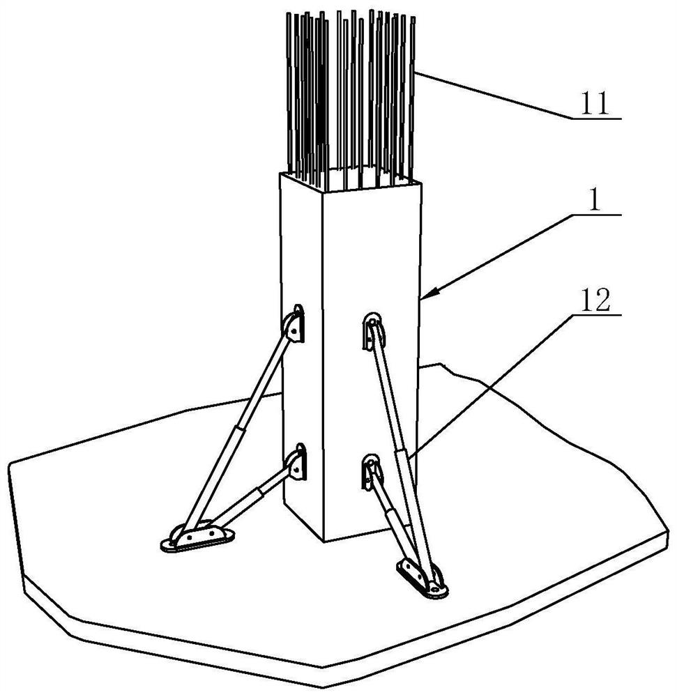
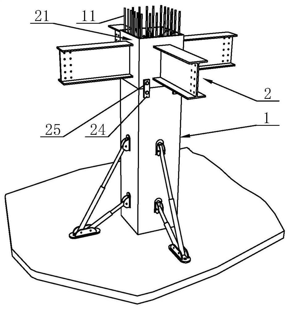
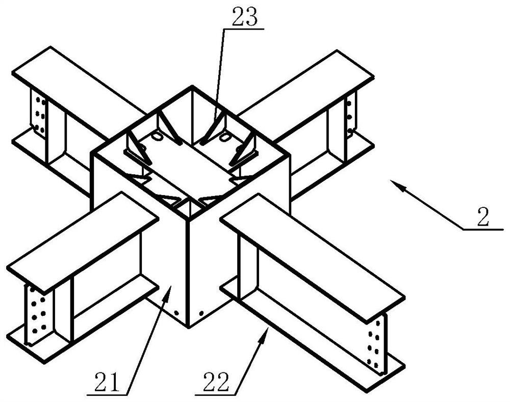
The invention discloses a construction method for a prefabricated frame structure system, and belongs to the technical field of prefabricated buildings. The construction method comprises the following steps that a plurality of prefabricated concrete columns are arranged at intervals, and grouting sleeves are arranged at the bottoms of the prefabricated concrete columns; reserved reinforcing steel bars corresponding to the grouting sleeves are pre-embedded at the tops of the prefabricated concrete columns, specifically, prefabricated beam column joints are hoisted, each prefabricated beam column joint comprises a hoop plate, a penetrating steel beam and stiffening ribs, the prefabricated beam column joints are wholly hoisted to the positions above the prefabricated concrete columns, and the reserved reinforcing steel bars penetrate through the interiors of the hoop plates in the vertical direction; then the outer walls of the hoop plates are connected to the prefabricated concrete columns together through fasteners and limiting plates; frame beams and secondary beams are mounted; a steel bar truss floor support plate is mounted; and floor concrete is poured. The construction method has the advantages of beam penetration and column penetration; and components are fully prefabricated, assembling is simple, and on-site construction and mounting are convenient.

Description

technical field [0001] The invention belongs to the technical field of prefabricated buildings, and in particular relates to a construction method of a prefabricated frame structure system. Background technique [0002] With the continuous development of building structure forms, more and more new hybrid frame structures have emerged. Reinforced concrete column-steel beam composite frame structure (reinforced concrete column-steel beam, referred to as RCS composite frame structure) combines the advantages of traditional steel structure and reinforced concrete frame structure, so it is more and more widely used in engineering applications. Compared with the steel structure, it has the characteristics of saving steel and increasing the rigidity of the building. At the same time, it has higher stability and durability; specialty. In order to ensure reliable force transmission between reinforced concrete columns and steel beams, a reasonable structural form is very important. ...

Claims


Application Information

Patent Timeline
Patent Type & Authority Applications(China)
IPC IPC(8): E04B1/58E04B1/30
CPCE04B1/58E04B1/30E04B1/5812E04B1/5831
Inventor 徐鹏强李飞李庆堂宁娜娜董丽萍林萌刘晓燕李希文
Owner CHANGDA BUILDING MATERIAL CO LTD
Why Eureka
Try Eureka