Zoom lighting device

A lighting device and accommodating slot technology, applied in the field of lighting, can solve the problems of low utilization rate of light, low brightness, etc.

Active Publication Date: 2021-09-07
SHENZHEN HENGZHIYUAN TECH CORP LTD
View PDF6 Cites 1 Cited by
  • Summary
  • Abstract
  • Description
  • Claims
  • Application Information

AI Technical Summary

Problems solved by technology

[0005] Regarding the related technologies mentioned above, the inventor believes that there is such a way of switching between high beam and low beam, and the u

Method used


Image

  • Zoom lighting device
  • Zoom lighting device

Examples


Embodiment Construction

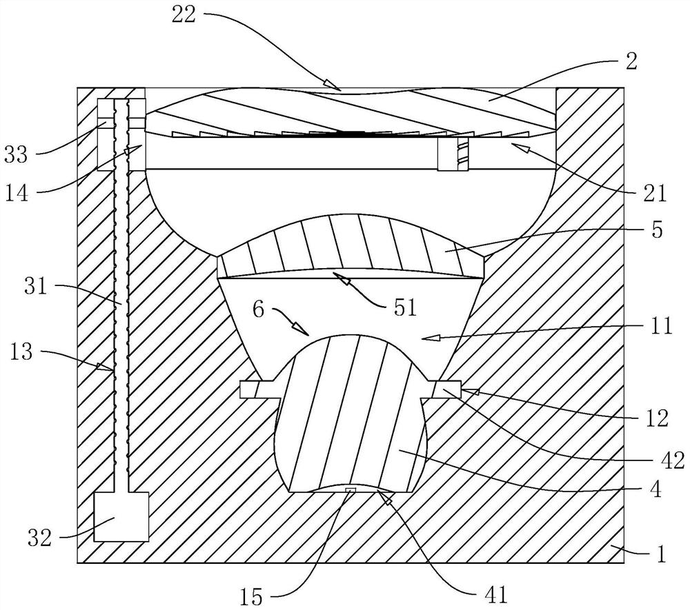
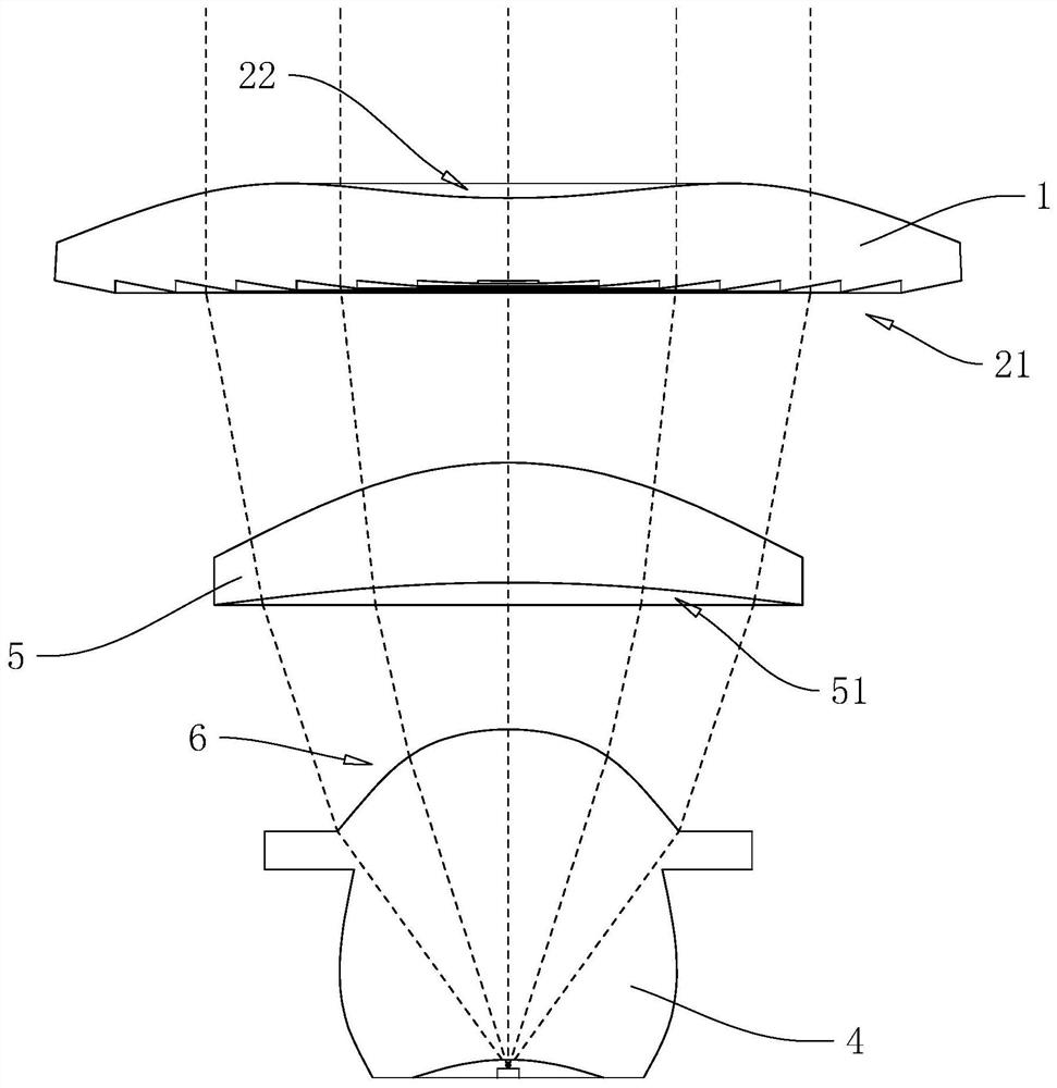
[0034] The following is attached Figure 1-2 The application is described in further detail.

[0035]The embodiment of the present application discloses a zoom lighting device. refer to figure 1 and figure 2 The zoom lighting device includes a cover body 1, a light source 15 and a plurality of convex lenses. Specifically, one side of the cover body 1 is provided with an accommodating groove 11 for installing components, and the light source 15 is fixed on the bottom of the accommodating groove 11. In this embodiment, there are three convex lenses, including the second convex lens 4. Specifically, the second convex lens 4 is fixed on the bottom of the accommodating groove 11, and the second convex lens 4 is close to the groove of the accommodating groove 11. One end of the bottom is integrally provided with an avoidance groove 41, and the notch of the avoidance groove 41 abuts against the groove bottom of the accommodation groove 11, so that the light source 15 is in the cl...


PUM


Abstract

The invention relates to a zoom lighting device, which comprises a cover body, a light source, a first convex lens and a driving assembly, and the cover body is provided with a containing groove used for installing components; the light source is arranged in the containing groove; the first convex lens is slidably arranged in the containing groove and located on the side, close to a groove opening of the containing groove, of the light source; and the driving assembly is arranged on the cover body and used for enabling the first convex lens to move in the direction close to or away from the light source. According to the invention, the purpose of switching the high beam and the low beam is achieved, and meanwhile, the light of the light source is fully utilized.

Description

technical field [0001] The present application relates to the field of lighting technology, in particular to a zoom lighting device. Background technique [0002] A rail car is a means of transportation that can run on the track. At night, it is necessary to turn on the lights of the rail car to provide a view, and at the same time provide a certain reminder to the outside world to increase the safety of the vehicle during driving. And in actual use, rail car lights also need to have the function of switching between high beam and low beam to cope with different external environments. [0003] In the related art, the rail car light includes a cover body, a light source, a convex lens and a sunshield. The cover body is provided with a housing groove, and the material of the housing body can make the light emitted by the light source inside the housing tank only come from the housing tank. The light source is set in the accommodation groove, the convex lens is fixedly arrange...

Claims


Application Information

Patent Timeline
IPC IPC(8): F21S41/275F21S41/63F21W102/13F21W102/20F21W107/10
CPCF21S41/635F21S41/275F21W2102/13F21W2102/20F21W2107/10
Inventor 李昊东陈文涛高涛侯洪才李宇
Owner SHENZHEN HENGZHIYUAN TECH CORP LTD
Why Eureka
Try Eureka