Eureka AIR delivers breakthrough ideas for toughest innovation challenges, trusted by R&D personnel around the world.

Lidar device

A laser radar and equipment technology, applied in optics, optical components, nonlinear optics, etc., can solve the problems of reducing the operating distance of laser radar equipment and improving beam divergence

Pending Publication Date: 2021-09-07
ROBERT BOSCH GMBH
View PDF0 Cites 0 Cited by
  • Summary
  • Abstract
  • Description
  • Claims
  • Application Information

AI Technical Summary

Problems solved by technology

However, in this range of radiation angles, the effective aperture of the optical phase array is also reduced by 50%, and thus the beam divergence is increased
This reduces the range of the lidar device

Method used


Image

  • Lidar device
  • Lidar device
  • Lidar device

Examples


Embodiment Construction

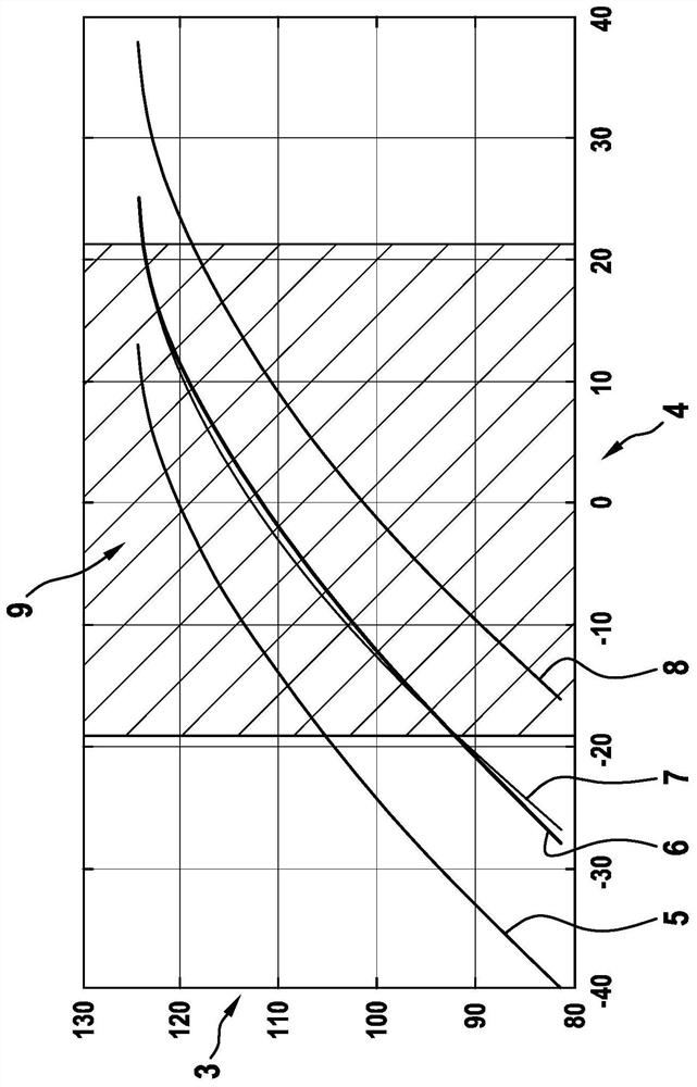
[0023] In conventional lidar devices of the prior art it is possible to ascertain which wavelength range is required for the emitted electromagnetic radiation to cover a predetermined field of view. This will be illustrated based on a vertical field of view of 20° as an example. This field of view is often required in automotive applications. In this case, the deflection of the electromagnetic radiation generally takes place via the wavelength of the electromagnetic radiation. This is based on the Bragg effect of the grid couplers of conventional lidar devices. The dependence of the radiation angles can then be calculated as follows:

[0024] sinθ=n eff -m*λ 0 / Λ.

[0025] Here, Λ is the grid period; n eff is the average effective refractive index in the grid area; λ 0 is the optical vacuum wavelength, and θ is the radiation angle to the grid normal at which the emission takes place. The factor m accounts for the diffraction order. Here, the Bragg grating coupler is pre...


PUM


Abstract

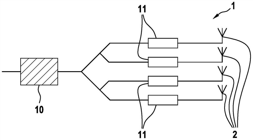
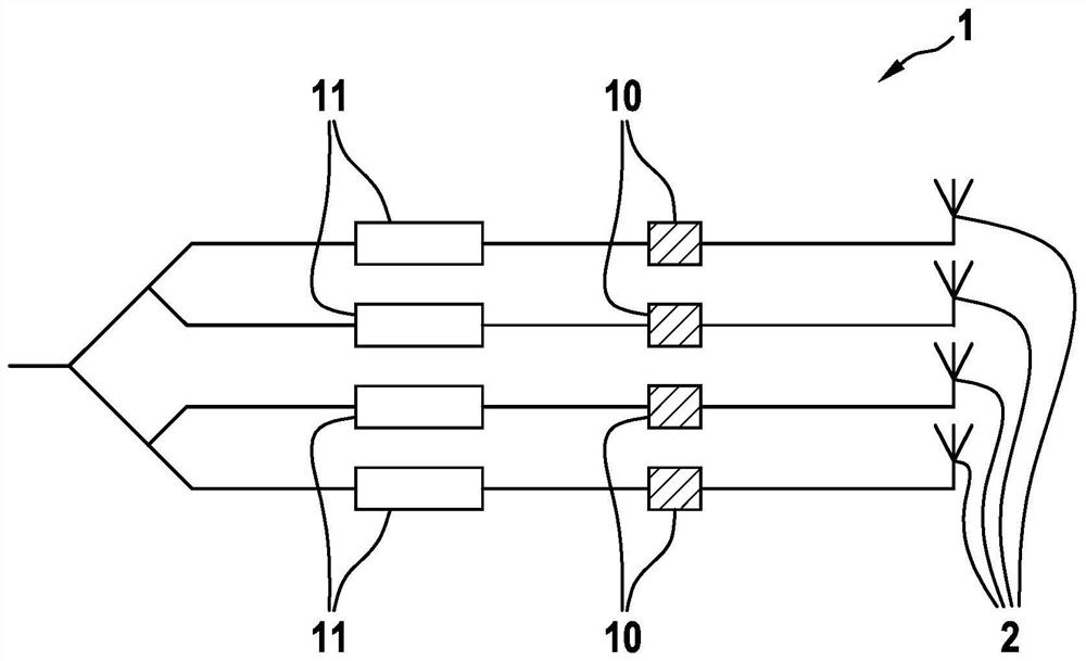
A lidar device is described having an integrated optical device that has a beam deflecting unit having an optical phase array (1) that has a multiplicity of antennas (2) that are set up to emit electromagnetic radiation at a prespecified angle of radiation. The angle of radiation covers a prespecified field of view of the lidar device. The angle of radiation has a first angle of radiation subregion, in which electromagnetic radiation is emitted having a polarization A, and has a second angle of radiation subregion, in which electromagnetic radiation is emitted having a polarization B.

Description

technical field [0001] The invention relates to a lidar device with integrated optics, which has a beam deflection unit with an optical phase array with a plurality of antennas, which are arranged for Electromagnetic radiation is emitted at a predetermined radiation angle, wherein the radiation angle covers a predetermined field of view of the lidar device. Background technique [0002] Micro-optical systems are the subject of much current research in the field of microsystems technology. Here, in particular, so-called integrated optics offer the possibility of guiding and processing electromagnetic radiation (light) in very compact planar waveguides. Here, the physical basis for guiding the electromagnetic radiation is similar to optical cables known per se. The LiDAR device has a beam deflection unit with an optical phase array. The beam deflecting unit can be used as a replacement for conventional mechanical mirrors. The beam deflection unit is significantly more resi...

Claims


Application Information

Patent Timeline
Patent Type & Authority Applications(China)
IPC IPC(8): G01S7/4911G01S7/481
CPCG01S7/4911G01S7/481G02F1/292G02F1/31G01S7/4817G01S7/499G02B27/286G02F2203/24G02F2203/07
Inventor J·N·卡斯佩斯S·施耐德
Owner ROBERT BOSCH GMBH
Why Eureka
Eureka Blog
Learn More