Arrangement for the Transmission of Magnetic Resonance Signals

a technology of magnetic resonance signal and arrangement, which is applied in the direction of geological measurements, using reradiation, sensors, etc., can solve the problems of enlarge the dynamic range of the system, reduce the spectral bandwidth of compressed signals, and restrict the bandwidth of compressor output signals

Active Publication Date: 2014-03-06
SIEMENS HEALTHCARE GMBH
View PDF3 Cites 16 Cited by
  • Summary
  • Abstract
  • Description
  • Claims
  • Application Information

AI Technical Summary

Benefits of technology

[0016]The spectral bandwidth of the compressed signal may be considerably reduced (e.g., from 50 MHz to 5 MHz) while at the same time satisfying the requirements relating to linearity and spectral purity of the expanded signal. This enlarges the dynamic range of the system due to the absence of noise interfolding.
[0017]The bandwidth of the compressor output signal is restricted as narrowly as possible. The combination of analog amplitude compression and subsequent band limiting allows the use of ADCs with a small bit depth.

Problems solved by technology

This enlarges the dynamic range of the system due to the absence of noise interfolding.

Method used


Image

  • Arrangement for the Transmission of Magnetic Resonance Signals
  • Arrangement for the Transmission of Magnetic Resonance Signals
  • Arrangement for the Transmission of Magnetic Resonance Signals

Examples


Embodiment Construction

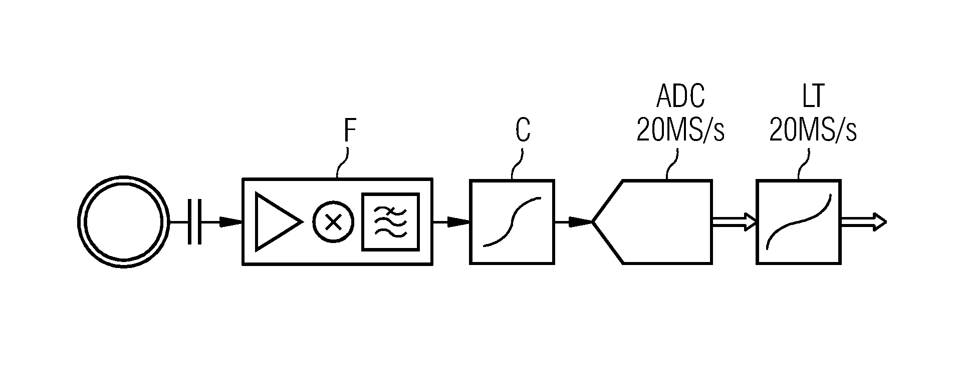
[0037]The elements of an embodiment of a compander system are shown in accordance with FIG. 4. The elements include the following disposed in series: a front end F, a compressor C, a low-pass filter LPF, an analog / digital converter ADC, an equalizer EQU for frequency response correction, a unit SAM for up-sampling (e.g., data rate conversion) and interpolation, a look-up table LT and a unit DEC for decimation.

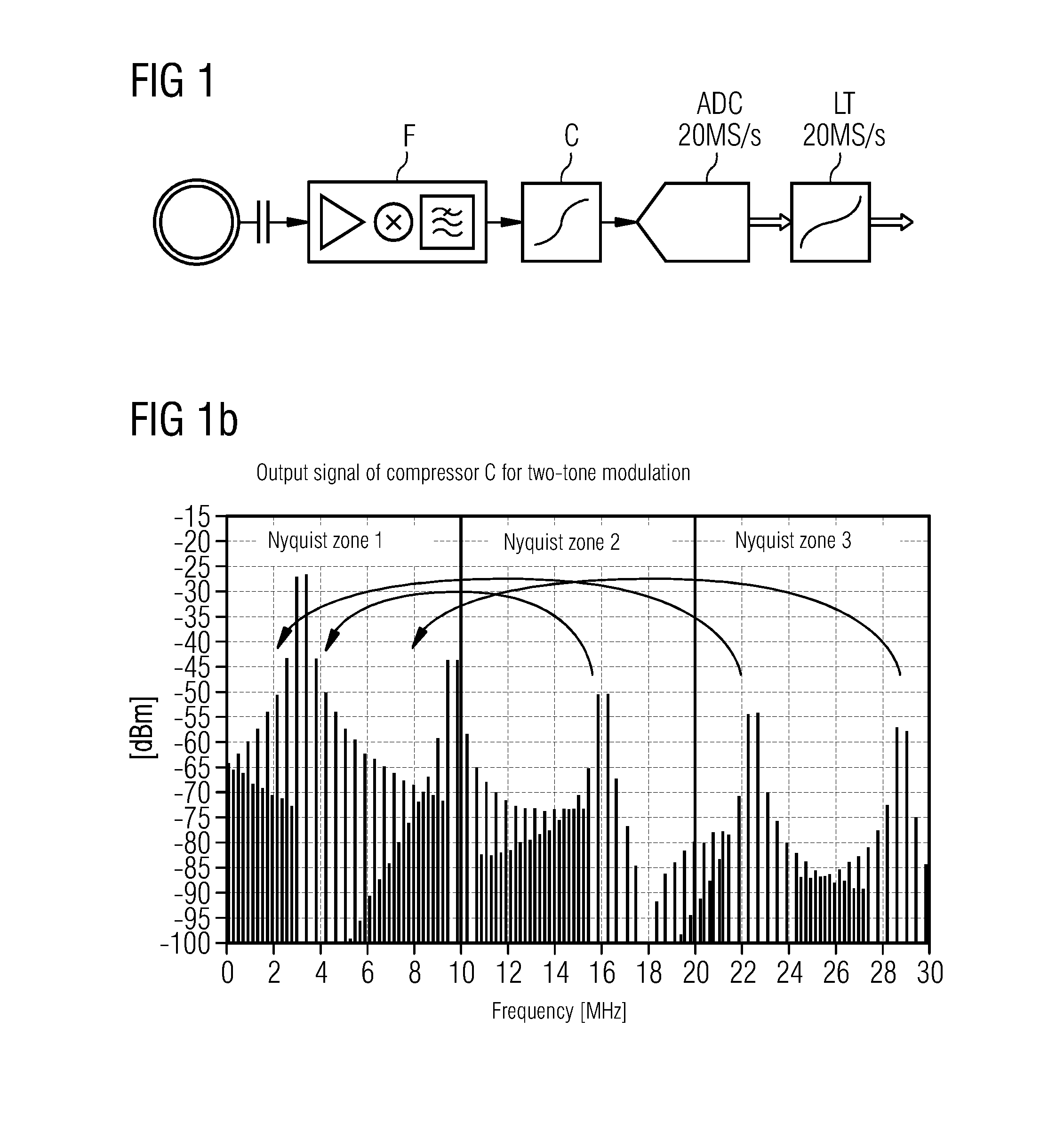
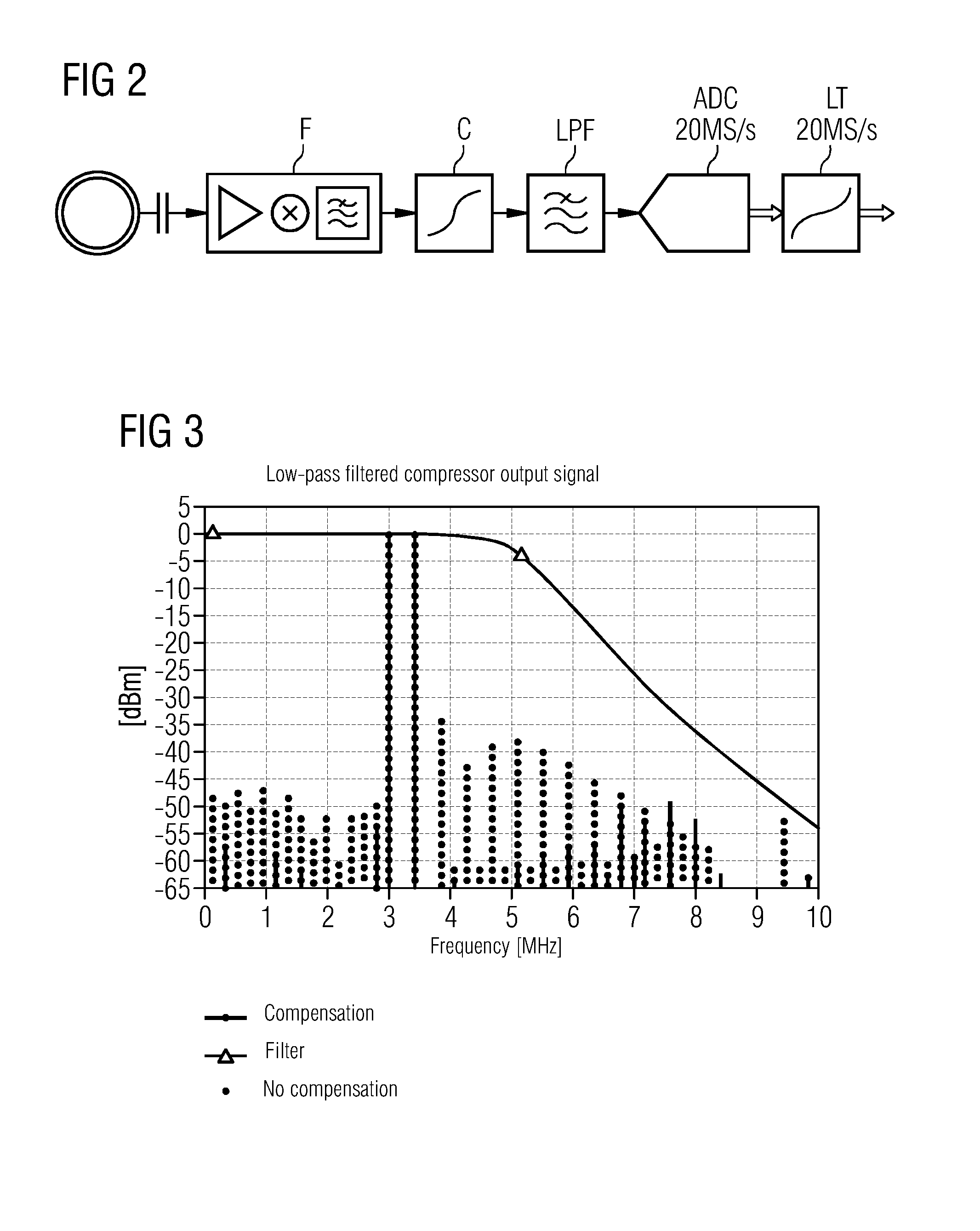
[0038]Harmonic components may occur during signal expansion and are folded into a first Nyquist sampling zone during sampling in discrete time. Disruptive interfolding is a function of a clock rate of the expander. The data or clock rate may be increased after sampling but before expansion (e.g., by the unit SAM for up-sampling and interpolation). The harmonic components therefore remain in the baseband and may be filtered before subsequent decimation.

[0039]This procedure is advantageous when the A / D converter ADC is disposed in the local coil. The sampling rate may be set low....


PUM


Abstract

An arrangement for the transmission of magnetic resonance signals that are received with the aid of local coils is provided. The magnetic resonance signal is fed to an analog/digital converter and digitized by the analog/digital converter. The magnetic resonance signal is compressed in amplitude before being fed to the analog/digital converter, is low-pass filtered or band-pass filtered, and is expanded after digitization by the analog/digital converter. A clock rate that is higher by a factor 2n than a sampling rate n of the analog/digital converter (ADC) is used for the digital expander. A digital equalizing filter for compensating for a filter transmission function in a transition range may also be used.

Description

[0001]This application claims the benefit of DE 10 2012 215 726.3, filed on Sep. 5, 2012, which is hereby incorporated by reference in its entirety.BACKGROUND[0002]The present embodiments relate to an arrangement for the transmission of magnetic resonance signals received with the aid of local coils.[0003]Modern magnetic resonance units simultaneously receive a plurality of magnetic resonance (MR) signals via local coils that are positioned on patients. The local coils are part of a local coil array. The received magnetic resonance signals are preamplified, conducted from a central region of the magnetic resonance unit and fed to a shielded receiver, to be used at the shielded receiver for image processing.[0004]Magnetic resonance signals have a high signal dynamic range, some of which covers more than 150 dBHz. In order to be able to process such signals without any perceptible deterioration of the signal-to-noise ratio, the components used to process the signal have an available d...

Claims


Application Information

Patent Timeline
Patent Type & Authority Applications(United States)
IPC IPC(8): G01R33/54
CPCG01R33/54G01R33/3415G01R33/3621G01R33/3692A61B5/055
Inventor BOLLENBECK, JANOPPELT, RALPHVESTER, MARKUS
Owner SIEMENS HEALTHCARE GMBH
Why Eureka
Try Eureka