Projection screen connection control method and electronic equipment

A technology for connection control and access point equipment, which is applied in the field of screen projection connection control methods and electronic equipment, and can solve problems such as easy to be maliciously used by people, projection screen connection interference, etc.

Active Publication Date: 2021-09-07
HONOR DEVICE CO LTD
View PDF5 Cites 9 Cited by
  • Summary
  • Abstract
  • Description
  • Claims
  • Application Information

AI Technical Summary

Problems solved by technology

This kind of preemption logic is flawed in design, and it is easy to be maliciously used by people, causing interference to the normal use of the screen projection connection

Method used


Image

  • Projection screen connection control method and electronic equipment
  • Projection screen connection control method and electronic equipment
  • Projection screen connection control method and electronic equipment

Examples


Embodiment ( 1

[0121] Embodiment (1) of the present application provides a screen projection connection control method, such as Image 6 As shown, the method may include step S301-step S303.

[0122] In step S301, the receiver device sends preemptive capability information to the sender device, and the preemptive capability information includes whether the receiver device supports preemptive screen projection connection.

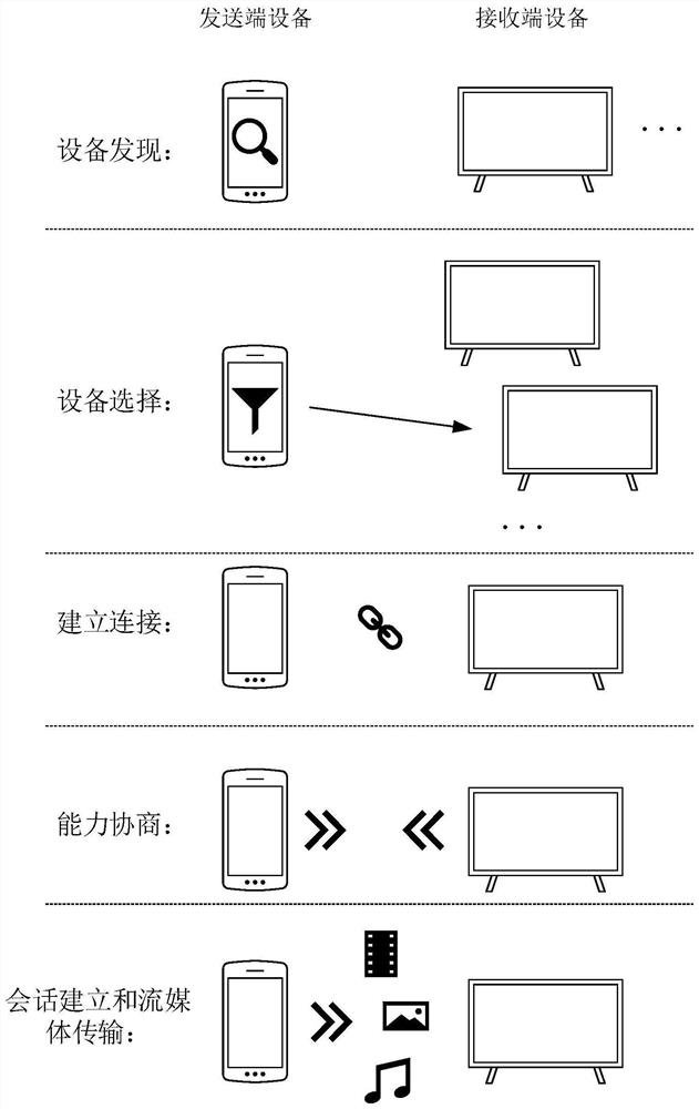
[0123] Among them, the receiver device can be in figure 2 In the "device discovery" stage, the preemption capability information is sent to the sending device.

[0124] In one implementation, such as Figure 7 As shown, when the sending end device discovers the receiving end device by means of passive scanning, the receiving end device can periodically broadcast a beacon frame (Beacon Frame) in the network, and carry preemption capability information in the beacon frame to inform its existence ; The sending end device discovers the receiving end device by monitoring th...

Embodiment ( 2

[0172] In Embodiment (2) of the present application, the receiver device configures its own preemption capability according to the device identifier of the sender device.

[0173] Figure 20 A flow chart showing that the receiver device configures its own preemption capability according to the device identifier of the sender device. The process is as Figure 20 The shown may include step S401-step S4032:

[0174] Step S401, when receiving a connection request, the receiving device obtains the device identifier of the sending device.

[0175] In a specific implementation, the device identifier of the sender device may be the device name, device number, SSID, MAC address, IP address and combinations thereof of the sender device. Wherein, the device name may specifically be a device model, a manufacturer name, and other user-defined names of the sending end device. It should be understood that the embodiment of the present application does not specifically limit the implement...

Embodiment ( 3

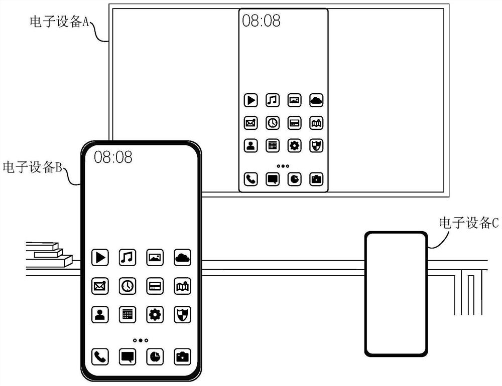
[0196] In some scenarios, the same user may own multiple electronic devices, such as at least one mobile phone, and / or at least one laptop, etc., and the user may successively use the above multiple electronic devices as the sending end device due to demonstration needs. Cast the screen on the receiving device. For example: during the period from t0 to t1, the user uses the sending device A (such as a mobile phone) to cast the screen on the receiving device; during the period from t1 to t2, the user uses the sending device B (such as a laptop) to cast Screencast on the device. In this case, if the sending-end device A sets the receiving-end device to not support connection preemption through the first configuration information within the time period t0-t1, then the sending-end device B needs to disconnect the receiving-end device from the sending-end device A. After the screen projection connection is enabled, the screen projection connection can be established with the recei...


PUM


Abstract

The invention provides a projection screen connection control method and electronic equipment. The method comprises the following steps: sending end equipment obtains preemption capability information of a receiving end device, wherein the preemption capability information indicates whether the receiving end device supports preemption projection screen connection or not; and when the receiving end equipment supports the preemptive screen projection connection, the sending end equipment sends first configuration information to the receiving end equipment in response to a user instruction, so that the receiving end equipment is configured to not support the preemptive screen projection connection. According to the technical scheme of the invention, the sending end equipment can obtain the preemption capability of the receiving end equipment, so that the sending end equipment can dynamically configure the preemption capability of the receiving end equipment according to the preemption capability of the receiving end equipment and user requirements. For example, if the user does not want to preempt the projection screen connection, the sending end equipment can configure the receiving end device to be not support preemption, so that the content delivered by the user on the receiving end equipment is prevented from being interfered or interrupted, the preemption logic of the streaming media projection screen scene is optimized, and the user experience is improved.

Description

technical field [0001] The present application relates to the technical field of streaming media transmission, and in particular to a screen projection connection control method and electronic equipment. Background technique [0002] Streaming media projection, also known as screencasting, projection, etc., refers to the use of relevant transmission protocols to mirror the screen, video, etc. Streaming media content such as , audio or image, is projected to another electronic device (such as smart TV, smart speaker, projector, etc.) through a network connection, so that another electronic device can play the same content in real time. [0003] Transmission protocols used to implement streaming media projection include Miracast, Digital Living Network Alliance (DLNA), AirPlay, and other private projection protocols. An electronic device generally supports preempting a screen projection connection when casting a screen. Among them, preempting the projection connection means ...

Claims


Application Information

Patent Timeline
Patent Type & Authority Applications(China)
IPC IPC(8): G06F3/14G06F3/0482H04N21/4363H04N21/643
CPCG06F3/1454G06F3/0482H04N21/43637H04N21/643G09G2370/042G09G2370/16G09G3/002G06F3/0488H04N21/43615H04W76/14
Inventor 王浩曹迅
Owner HONOR DEVICE CO LTD
Why Eureka
Try Eureka