
Drilling equipment for wooden mounting handle

A technology for punching equipment and handles, which is used in wood processing appliances, stationary drilling machines, forming/shaping machines, etc., can solve problems such as inconvenient collection and inconvenience in fixing

Active Publication Date: 2021-09-10
仙游县龙虎山古典家俱有限公司
View PDF5 Cites 1 Cited by
  • Summary
  • Abstract
  • Description
  • Claims
  • Application Information

AI Technical Summary

Problems solved by technology

[0005] In order to overcome the shortcomings of the prior art that manual punching is inconvenient to fix and collect, the technical problem is to provide a wooden installation handle punching device that can be automatically fixed and is easy to collect

Method used


Image

  • Drilling equipment for wooden mounting handle
  • Drilling equipment for wooden mounting handle
  • Drilling equipment for wooden mounting handle

Examples


Embodiment 1

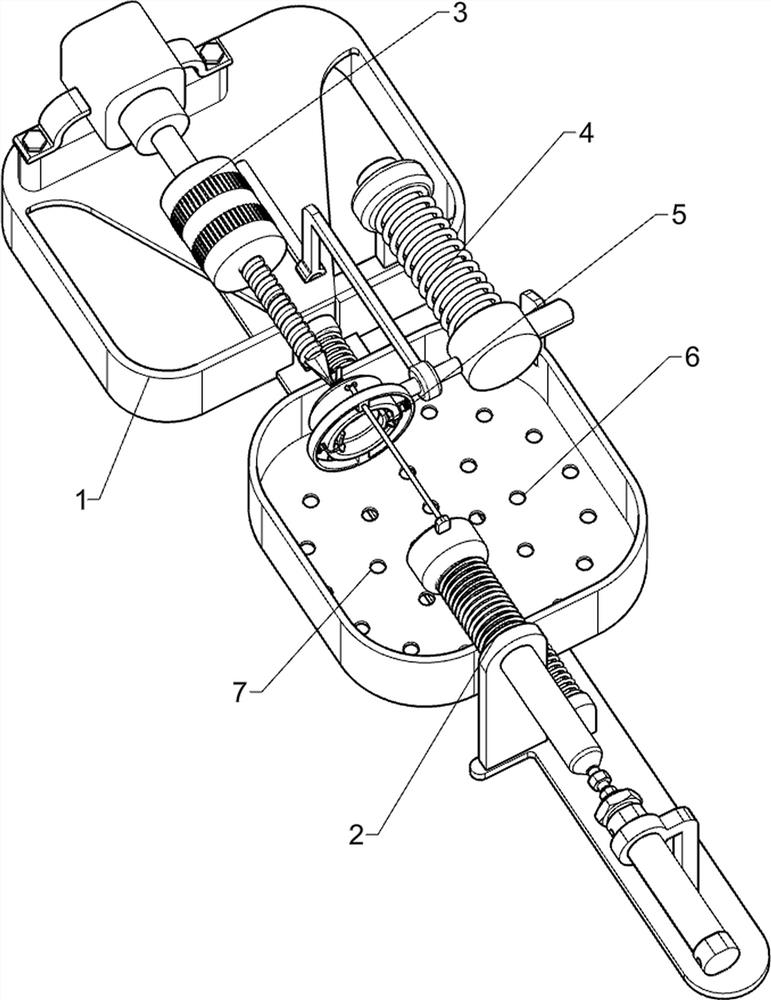
[0027] A wooden mounting handle punching device such as figure 1 , figure 2 and image 3 As shown, it includes a base 1 , a pushing mechanism 2 and a punching mechanism 3 , the pushing mechanism 2 is arranged on the top right side of the base 1 , and the punching mechanism 3 is arranged on the left side of the top of the base 1 .

[0028] When people need to punch holes in the wooden installation handle, this device can be used. First, the wooden installation handle is placed on the push mechanism 2. After the punching mechanism 3 is started, the push mechanism 2 is started again, and the push mechanism 2 will drive the wooden installation handle. Move to the left, when the punching mechanism 3 is in contact with the wooden installation handle, it will punch holes. After the punching is completed, close the push mechanism 2, and then close the punching mechanism 3, manually take out the wooden installation handle that has been punched, and arrange it That's it.

[0029] Th...

Embodiment 2

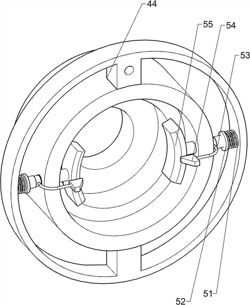
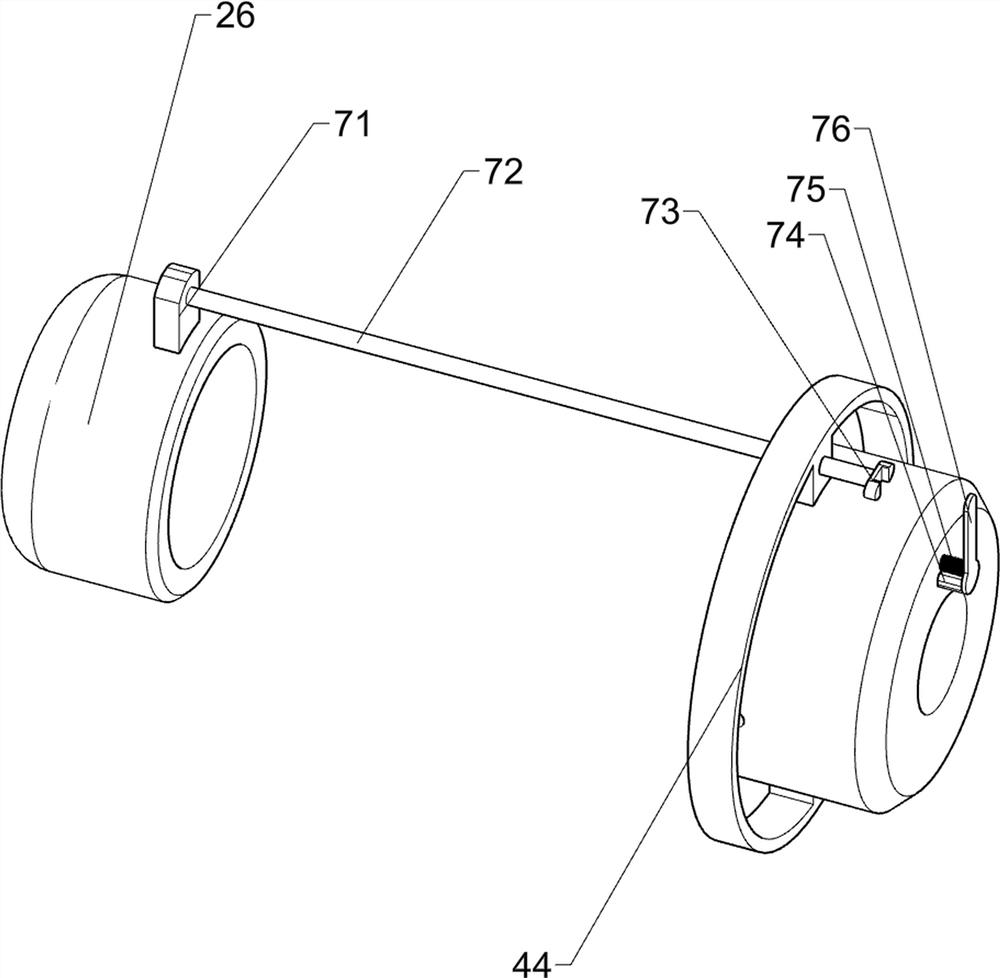
[0034] On the basis of Example 1, such as Figure 4 , Figure 5 , Figure 6 and Figure 7 As shown, a fixing mechanism 4 is also included, and the fixing mechanism 4 includes a third support column 41, a slide bar 42, a first connecting rod 43, a fixed frame 44, a first connecting block 45, a first top block 46, a second spring 47. The first guide rod 48 and the connecting collar 49, the top of the base 1 is provided with a sliding rod 42, the sliding rod 42 is provided with a third supporting column 41, and the right side of the third supporting column 41 is provided with a first connecting rod 43 , the front side of the first connecting rod 43 is provided with a fixed frame 44, the left rear side of the top of the base 1 is provided with a connecting collar 49, and the right side of the connecting collar 49 is slidably provided with a first guide rod 48, and the right side of the first guide rod 48 A first connecting block 45 is provided, the first connecting block 45 is ...


PUM


Abstract

The invention relates to drilling equipment, in particular to drilling equipment for a wooden mounting handle. According to the technical purpose, the drilling equipment for the wooden mounting handle aims to be capable of achieving automatic fixing and facilitating collection. According to the technical scheme, the drilling equipment for the wooden mounting handle comprises a base, a pushing mechanism and a drilling mechanism; and the pushing mechanism is arranged on the right side of the top of the base, and the drilling mechanism is arranged on the left side of the top of the base. The drilling equipment has the advantages of being capable of achieving automatic fixing and faciliating collection; and a piston rod of an air cylinder drives a first push block to move leftwards, the first push block pushes the wood mounting handle into a fixing frame, the clamping block fixes the wood mounting handle, and the automatic fixing effect is achieved.

Description

technical field [0001] The invention relates to a punching device, in particular to a punching device for a wooden installation handle. Background technique [0002] After the trees are felled, they can be used as materials for construction and making utensils after preliminary processing. Wood drilling is a very common process, and before drilling holes for wooden handles, people need to cut and polish the wood , After cutting and sanding the wood to the size of a handle, the drilling process begins. [0003] But in the prior art, when using the drill bit to drill wood, because the drill bit rotates faster and the handle is smaller, it is easy to cause people's hands to be injured during the drilling process, and it cannot be fixed in a certain place for punching. , and the handle and the falling sawdust are inconvenient for people to collect. [0004] In view of the above-mentioned problems in the prior art, it is necessary to design a wooden installation handle punching...

Claims


Application Information

Patent Timeline
IPC IPC(8): B27C3/02B27C5/06
CPCB27C3/02B27C5/06Y02P70/10
Inventor 宋秋妹
Owner 仙游县龙虎山古典家俱有限公司
Learn More