
Injection molding sprue cutting device

A cutting-off device and gate technology, applied in the field of injection molding, can solve problems such as low efficiency and high labor intensity

Pending Publication Date: 2021-09-10
GREE ELECTRIC APPLIANCES WUHAN +1
View PDF0 Cites 0 Cited by
  • Summary
  • Abstract
  • Description
  • Claims
  • Application Information

AI Technical Summary

Problems solved by technology

[0005] The purpose of the present invention is to provide an injection molding gate cutting device, which solves the technical problems of high labor intensity and low efficiency in the prior art that separates the gate from the wind deflector by manual shearing

Method used


Image

  • Injection molding sprue cutting device
  • Injection molding sprue cutting device
  • Injection molding sprue cutting device

Examples


Embodiment Construction

[0033] In order to make the purpose, technical solution and advantages of the present invention clearer, the technical solution of the present invention will be described in detail below. Apparently, the described embodiments are only some of the embodiments of the present invention, but not all of them. Based on the embodiments of the present invention, all other implementations obtained by persons of ordinary skill in the art without making creative efforts fall within the protection scope of the present invention.

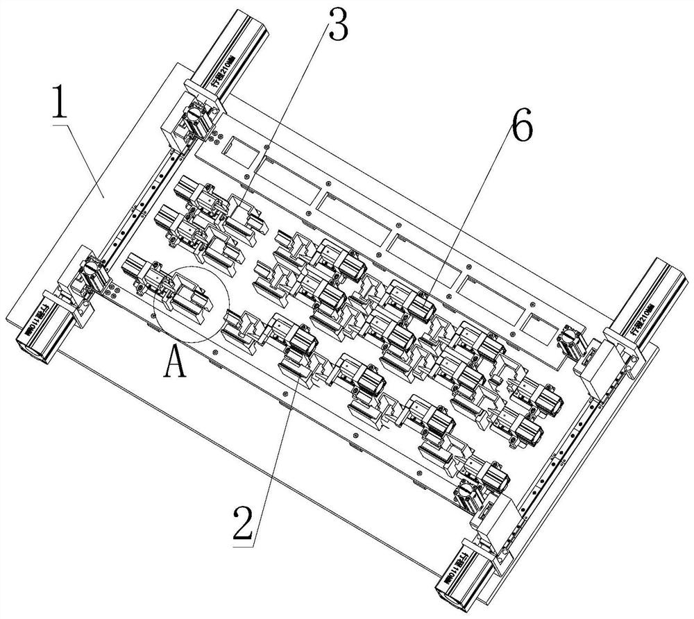
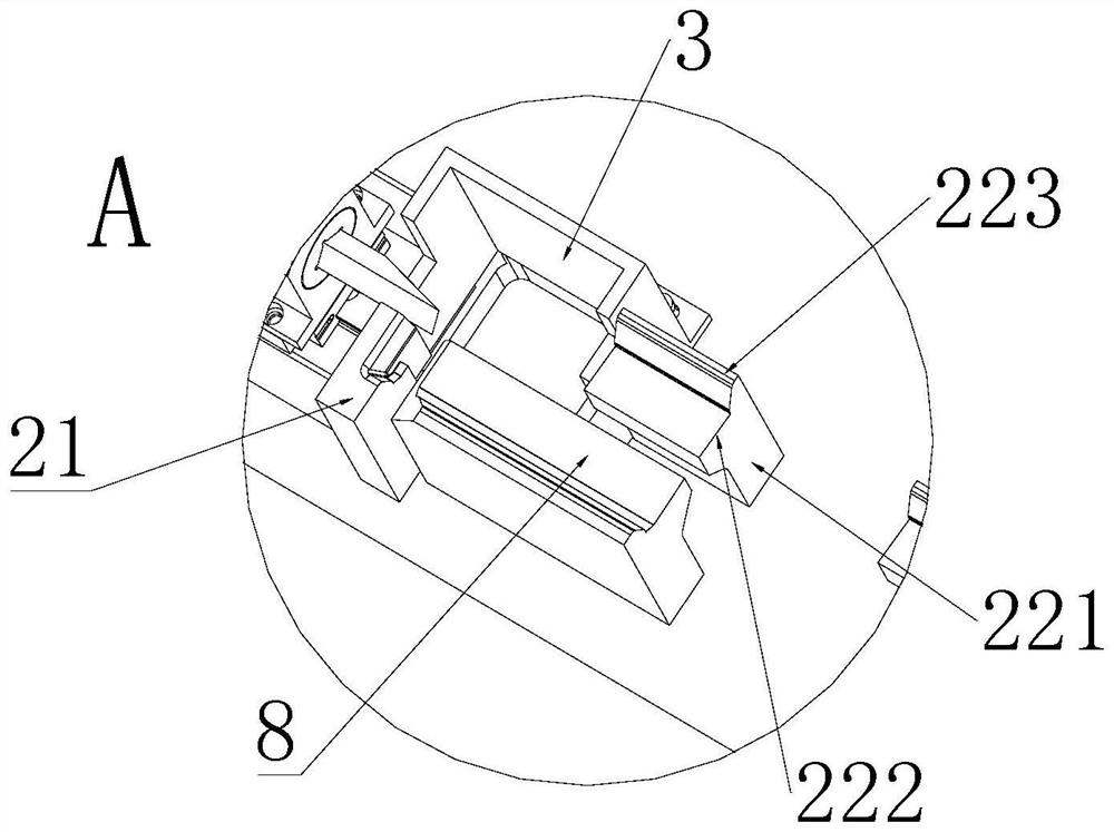
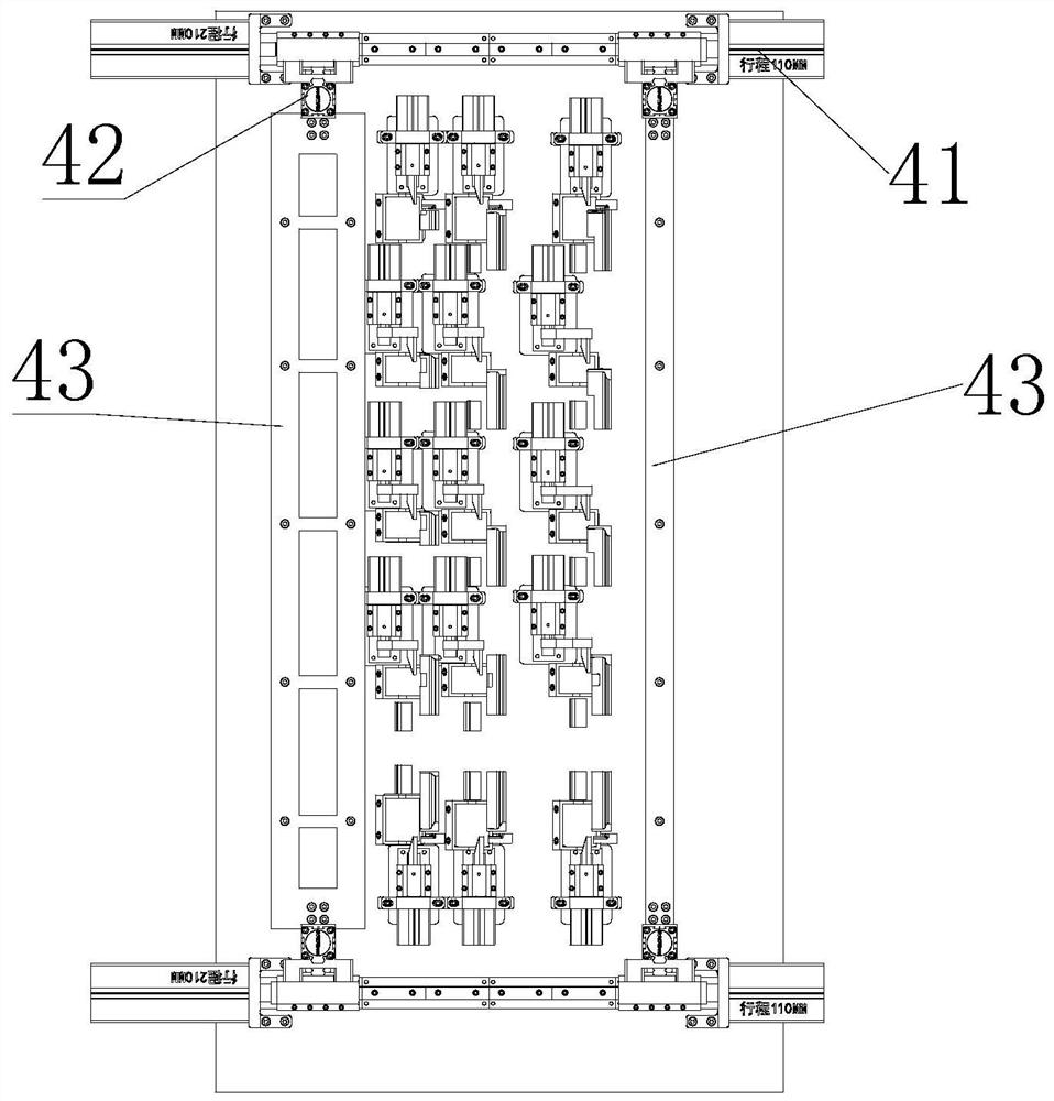
[0034] see Figure 1-Figure 7, the present invention provides an injection molding gate cutting device, including a base 1, a positioning assembly and a cutting assembly 6, wherein the positioning assembly includes a fixed support limiting part 2 and a gate limiting part 3 arranged on the base 1 and the moving limiter 4, the fixed support limiter 2 is formed with a support surface 8 for placing the air deflector assembly 5, when the air deflector assembly 5 is ...


PUM


Abstract

The invention provides an injection molding sprue cutting device, relates to the technical field of injection molding, and solves the technical problems of high labor intensity and low efficiency due to the fact that a sprue is separated from an air deflector in a manual shearing mode in the prior art. The device comprises a base, a positioning assembly and a cutting assembly, wherein, the positioning assembly comprises a fixed supporting limiting part, a sprue limiting part and a movable limiting part which are arranged on the base, a supporting face for containing an air deflector assembly is formed on the fixed supporting limiting part, and when the air deflector assembly is placed on the supporting face, the sprue of the air deflector assembly is located in the sprue limiting part, and the movable limiting part can move to the position above the air deflector assembly so as to be matched with the fixed supporting limiting part to limit the position of the air deflector assembly; and the cutting assembly is arranged on the base and can do reciprocating motion in the length direction of the air deflector assembly so as to cut the sprue. The device is used for achieving automatic separation of the sprue and the air deflector, the labor intensity is reduced, and the production efficiency is improved.

Description

technical field [0001] The invention relates to the technical field of injection molding, in particular to an injection molding gate cutting device. Background technique [0002] With the development of industrial automation, injection molded parts are used more and more widely in all walks of life, but the injection molding machine cannot process the finished product at one time, and the plastic liquid gate during injection molding will remain on the injection molded parts just removed from the mold. Removing these gate wastes from the product has become a major problem in completing the production of injection molded parts. [0003] For example, in the air-conditioning manufacturing industry, the air deflector is completed by injection molding with an injection molding machine. After the raw materials are put into the injection molding machine, after shearing and refining and high-temperature melting, the melted raw materials are injected into the hot runner of the mold th...

Claims


Application Information

Patent Timeline
Patent Type & Authority Applications(China)
IPC IPC(8): B29C45/38
CPCB29C45/382
Inventor 李超吴彬张强强焦海波周溪郭辉盛
Owner GREE ELECTRIC APPLIANCES WUHAN
Learn More