Large-current charging connection structure for ships

A charging connection, high-current technology, applied in electric vehicle charging technology, charging stations, electric vehicles, etc., can solve the problems of low flexibility, increased operator work intensity, complex docking and separation, etc.

Pending Publication Date: 2021-09-10
SGCC SMART ENERGY & ELECTRIC TRANSPORTATION TECH INNOVATION CENT (SUZHOU) CO LTD +1
View PDF0 Cites 0 Cited by
  • Summary
  • Abstract
  • Description
  • Claims
  • Application Information

AI Technical Summary

Problems solved by technology

[0002] Compared with the charging equipment of electric vehicles, the charging current of electric ships is larger when charging, and the battery capacity of ships is also much larger. In the prior art, in order to meet the charging needs of electric ships, special charging equipment ( Such as ship charging pile), when charging an electric ship, it is realized by connecting the charging connector of the charging equipment to the charging stand of the electric ship. It is necessary to set the charging connector and charging stand according to different charging equipment to adapt to different charging. Current, the docking of the charging connector and the charging stand is mostly rotary, the docking and separation are more complicated, which increases the work intensity of the operator, the flexibility is not strong, and the charging stability is poor, and it is easy to drop to cause charging interruption and affect the charging effect.

Method used


Image

  • Large-current charging connection structure for ships
  • Large-current charging connection structure for ships
  • Large-current charging connection structure for ships

Examples


Embodiment Construction

[0022] The preferred embodiments of the present invention will be described in detail below in conjunction with the accompanying drawings, so that the advantages and features of the present invention can be more easily understood by those skilled in the art, so as to define the protection scope of the present invention more clearly.

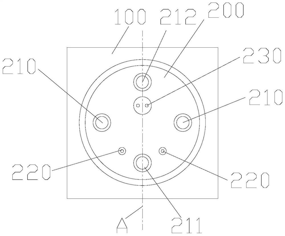
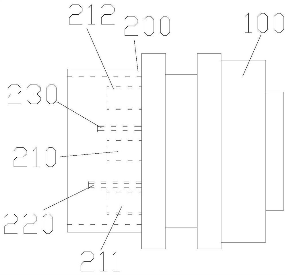
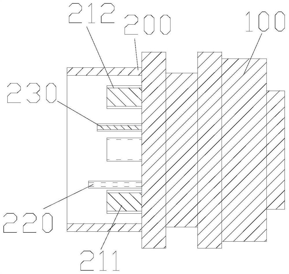
[0023] as attached figure 1 to attach image 3 As shown, the high-current charging connection structure for ships in this embodiment includes a charging connector 200 and a charging stand 300, and the charging connector 200 and the charging stand 300 are arranged in cooperation. There are slots, and the posts are arranged in cooperation with the slots, the charging connector 200 is connected to a charging device (such as a charging pile), and the charging stand 300 is set on the ship and connected to the battery pack of the ship.

[0024] The posts on the charging connector 200 include a power post 210, a control post 220, and a communication po...


PUM


Abstract

The invention discloses a large-current charging connection structure for ships, which comprises a charging connector and a charging seat, the charging connector comprises connecting columns, the charging seat comprises slots matched with the connecting columns, the connecting columns comprise a power connecting column, a control connecting column and a communication connecting column, the length of the power connecting column is smaller than that of the control connecting column, and the length of the communication connecting column is smaller than that of the power connecting column. The length of the control connecting column is smaller than that of the communication connecting column, the slots comprise a power slot matched with the power connecting column, a control slot matched with the control connecting column and a communication slot matched with the communication connecting column, and when the charging connector is connected with a charging base, the communication connecting column, the control connecting column and the power connecting column are sequentially connected. The charging and discharging control logic requirement is met, the position distribution of the connecting columns is adjusted, the charging connector and the charging base have the unique connecting mode, the connecting efficiency is improved, different charging requirements are met by connecting the charging connectors in parallel, and the flexibility is good.

Description

technical field [0001] The invention relates to the technical field of charging equipment, in particular to a large-current charging connection structure for ships. Background technique [0002] Compared with the charging equipment of electric vehicles, the charging current of electric ships is larger when charging, and the battery capacity of ships is also much larger. In the prior art, in order to meet the charging needs of electric ships, special charging equipment ( Such as ship charging pile), when charging an electric ship, it is realized by connecting the charging connector of the charging equipment to the charging stand of the electric ship. It is necessary to set the charging connector and charging stand according to different charging equipment to adapt to different charging. The connection between the charging connector and the charging stand is mostly rotary, and the connection and separation are more complicated, which increases the work intensity of the operato...

Claims


Application Information

Patent Timeline
IPC IPC(8): B60L53/16
CPCB60L53/16Y02T10/70Y02T10/7072Y02T90/14Y02T90/16
Inventor 宋锦海海晓涛贾俊国
Owner SGCC SMART ENERGY & ELECTRIC TRANSPORTATION TECH INNOVATION CENT (SUZHOU) CO LTD
Why Eureka
Try Eureka