A nanobubble-based sewage treatment device

A sewage treatment device and nano-bubble technology, applied in water/sewage multi-stage treatment, water/sludge/sewage treatment, filtration treatment, etc., can solve the large difference in aeration effect of micro-nano aeration tubes and shorten the service life , Poor aeration effect and other problems, to achieve the effect of improving poor aeration effect, reducing blockage, and equalizing air pressure

Active Publication Date: 2022-07-01
GUANGDONG UNIV OF TECH
View PDF11 Cites 0 Cited by
  • Summary
  • Abstract
  • Description
  • Claims
  • Application Information

AI Technical Summary

Problems solved by technology

In actual operation, too much pressurization of the micro-nano aeration tube will cause excessive expansion of the tube body, reducing the service life or even direct damage; too little pressurization will lead to poor aeration effect
And because the resistance pressure inside the pipeline is different, under the same pressure, the aeration effect of the micro-nano aeration tube is quite different.

Method used


Image

  • A nanobubble-based sewage treatment device
  • A nanobubble-based sewage treatment device
  • A nanobubble-based sewage treatment device

Examples


Embodiment 1

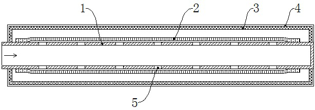
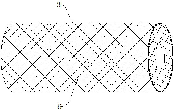
[0026] see figure 1 and 2 , this embodiment provides a nano-bubble-based sewage treatment device, including a rigid inner air pipe 1, one end of the rigid inner air pipe 1 is connected to the air source, and the other end is sealed; the outer side of the rigid inner air pipe 1 is sleeved with elastic micro Nano-aeration tube 2, both ends of the elastic micro-nano aeration tube 2 are airtightly connected with the outer side of the rigid inner air tube 1; corresponding to the side wall of the rigid inner air tube 1 in the elastic micro-nano aeration tube 2, a number of first ventilation holes 5 are provided. The outer side of the rigid inner trachea 1 is sleeved with a rigid holding pipe 3, the two ends of the rigid holding pipe 3 are fixedly connected to the outside of the rigid inner trachea 1, and the elastic micro-nano aeration pipe 2 is located in the rigid holding pipe 3. , there is a gap between the elastic micro-nano tube 2 and the rigid holding pipe 3; the rigid holdin...

Embodiment 2

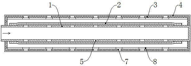
[0032] see image 3 and 4 , this embodiment provides a nano-bubble-based sewage treatment device, including a rigid inner air pipe 1, one end of the rigid inner air pipe 1 is connected to the air source, and the other end is sealed; the outer side of the rigid inner air pipe 1 is sleeved with elastic micro Nano-aeration tube 2, both ends of the elastic micro-nano aeration tube 2 are airtightly connected with the outer side of the rigid inner air tube 1; corresponding to the side wall of the rigid inner air tube 1 in the elastic micro-nano aeration tube 2, a number of first ventilation holes 5 are provided. The outer side of the rigid inner trachea 1 is sleeved with a rigid holding pipe 3, the two ends of the rigid holding pipe 3 are fixedly connected to the outside of the rigid inner trachea 1, and the elastic micro-nano aeration pipe 2 is located in the rigid holding pipe 3. , there is a gap between the elastic micro-nano tube 2 and the rigid holding pipe 3; the rigid holdin...


PUM


Abstract

The invention discloses a nano-bubble-based sewage treatment device, comprising a rigid inner trachea, one end of the rigid inner trachea is connected to an air source, and the other end is sealed; an elastic micro-nano aeration pipe is sleeved on the outer side of the rigid inner trachea The two ends of the elastic micro-nano aeration tube are airtightly connected to the outer side of the rigid inner trachea; the side walls of the rigid inner trachea corresponding to the elastic micro-nano aeration tube are provided with a number of first ventilation holes; the outer side of the rigid inner trachea is sleeved with hard Holding tube, both ends of the hard holding tube are fixedly connected to the outside of the hard endotracheal tube, the elastic micro-nano aeration tube is located in the hard holding tube, and there is a gap between the elastic micro-nano tube and the hard holding tube; the hard holding tube A number of ventilation channels are arranged; the outer side of the hard holding pipe is covered with a filter layer; the present invention is provided with a hard holding pipe on the outside of the micro-nano aeration pipe to limit the degree of expansion and expansion thereof, so as to improve the uniformity of the expansion of the micro-nano aeration pipe. Improve the aeration effect; in addition improve the uniformity of the air supply, and reduce clogging.

Description

technical field [0001] The invention belongs to the technical field of sewage treatment equipment, in particular to a sewage treatment device based on nano-bubble. Background technique [0002] A blower or an air compressor is used to transport the air into the water through the aeration pipe, and then disperse and escape in the form of bubbles, and the oxygen is dissolved into the water at the gas-liquid interface, which is a common method to provide dissolved oxygen in the water. [0003] Existing aeration tubes are divided into perforated aeration tubes and micro-nano aeration tubes. The perforated aeration pipe is a small hole with a diameter of millimeters or centimeters on both sides of the aeration pipe. During aeration, gas is ejected from the small holes on both sides to achieve the purpose of oxygenation and hydraulic disturbance; but the pores of the perforated aeration pipe The larger the pore size, the larger the bubbles formed, which is not conducive to the ma...

Claims


Application Information

Patent Timeline
Patent Type & Authority Patents(China)
IPC IPC(8): C02F7/00C02F9/02
CPCC02F7/00C02F1/001Y02W10/10
Inventor 冯力左明浩伍珅羽刘嘉俊刘冰枝李栩灏陈煜柠
Owner GUANGDONG UNIV OF TECH
Why Eureka
Try Eureka