
Medical vaginal dilator

A vaginal expansion and vaginal technology, applied in the field of medical devices, can solve the problems of high production cost, waste of materials, and difficult processing, etc., and achieve the effect of less production materials, simple structure and easy production

Pending Publication Date: 2020-07-10
杨庆军
View PDF0 Cites 0 Cited by
  • Summary
  • Abstract
  • Description
  • Claims
  • Application Information

AI Technical Summary

Problems solved by technology

At present, this commonly used vaginal dilator has a relatively complicated structure and is difficult to process. In addition, it is usually made of high-quality medical plastic with high strength, and the production cost is relatively high. The use of it as a disposable medical device greatly increases the cost of diagnosis and treatment of gynecological diseases; at the same time , Disposable after use also caused a serious waste of data
In addition, since both sides of the rear end of the upper and lower expansion wings are hinged, the opening at the rear end of the vaginal dilator is closed loop, which affects the openness of the surgical field, and the hinged part often hinders the operation of the instrument and the doctor's line of sight. , affecting the effectiveness and efficiency of diagnosis and treatment

Method used


Image

  • Medical vaginal dilator
  • Medical vaginal dilator
  • Medical vaginal dilator

Examples


Embodiment 1

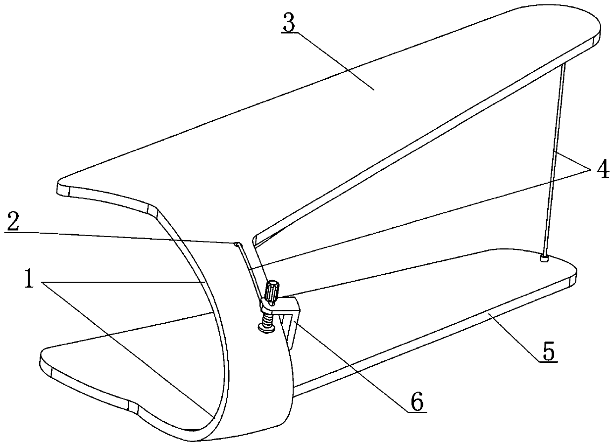
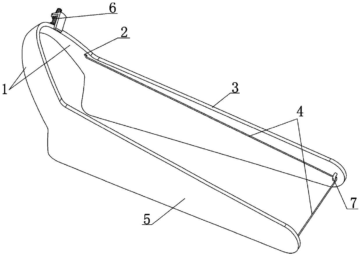
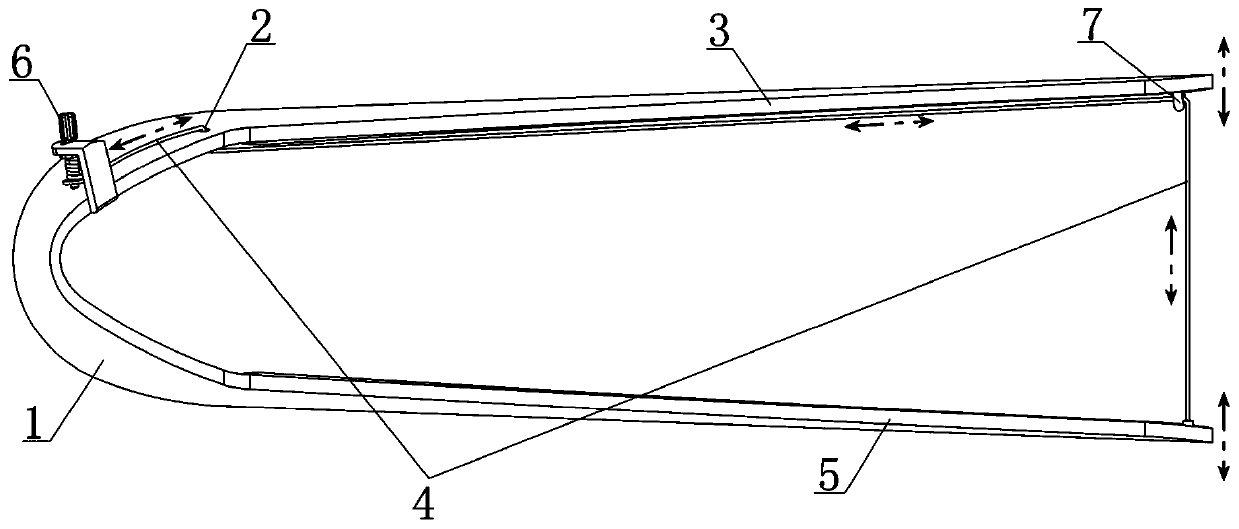
[0031] see Figure 1-4 As shown, this embodiment discloses a medical vaginal dilator, which includes an upper expansion wing 3 and a lower expansion wing 5. The upper expansion wing 3 and the lower expansion wing 5 have the same shape, and both of them are curved from front to back. The width gradually increases, and the upper expansion wing 3 and the lower expansion wing 5 cooperate to expand the vagina; the rear ends of the upper expansion wing 3 and the lower expansion wing 5 are located at the two corners on the same side through a curved bow 1 Connected; under the support of the bow portion 1, the upper expansion wing 3 and the lower expansion wing 5 are distributed in a duckbill shape, and the upper expansion wing 3 and the lower expansion wing 5 are in an open state when the aforementioned three are not subjected to external forces; The bow portion 1 is located behind the upper expansion wing 3 and the lower expansion wing 5, and the three are integrated, that is, the t...

Embodiment 2

[0050] see image 3 As shown, in the medical vaginal dilator, the twisted rope device 6 is the core component to realize the adjustment of the degree of expansion. It has been explained in Embodiment 1 that there is such a mechanism as the twisted rope device 6 in the prior art, and the prior art is also listed. The embodiment of twisted rope device 6 promptly adopts the structure of wire wheel and wire drum. Although the twisted rope device 6 in the prior art can meet its basic function requirements in the medical vaginal dilator, its structure is slightly complicated, which affects the compactness and simplicity of the medical vaginal dilator. The operation when reaching the braking state is more troublesome, and requires the cooperation of both hands, which is not convenient enough. If the operation is improper, the braking effect will be unstable, so that the medical vaginal dilator cannot maintain an ideal and constant expansion degree; for this reason, this embodiment A...

Embodiment approach

[0058] This embodiment provides another preferred embodiment of the twisted rope device 6, and the specific structure is as follows:

[0059] see Figure 10-12 As shown, the twisted rope device 6 includes two supports 19 and a winding shaft 16 connected to the tail end of the pulling wire 4; the two supports 19 are fixed on the upper side of the bow part 1 and are located in the threading hole 2; the bobbin 16 is supported by two supports 19, and one end of the bobbin 16 extends to the outside of the corresponding support 19 and is fixed with a handle 14, and an anti-rotation baffle is fixed on the bobbin 16 21 and a circular baffle plate 20, the anti-rotation baffle plate 21 and the circular baffle plate 20 are arranged at intervals and are all located between the two supports 19; It will be separated from the two supports 19; the support 19 close to the anti-rotation baffle 21 is provided with a limit seat 22 for accommodating the anti-rotation baffle 21, and the bobbin 16 ...


PUM


Abstract

The invention relates to the field of medical equipment, and specifically discloses a medical vaginal dilator. The medical vaginal dilator includes an upper expansion wing, a lower expansion wing, anda curved part for connecting two rear end corner parts of the upper expansion wing and the lower expansion wing; a threading ring is fixed on the inner side of the front end of the upper expansion wing, and the curved part is provided with a threading hole; the inner side of the front end of the lower expansion wing is fixedly connected with the front end of a pulling line; the tail end of the pulling line passes through the threading ring to extend to the outside of the curved part through the threading hole, and is finally connected with a line twisting device; and the line twisting deviceis artificially driven to wind and unwind the pulling line, so that the expansion degree of the medical vaginal dilator is adjusted. The medical vaginal dilator is simple in structure, easy to prepare, low in costs, and extremely suitable for one-time use; the medical vaginal dilator can obtain an open surgical field during clinical use, and can reduce the hindrance to clinical diagnosis and treatment operation; and the expansion force of the medical vaginal dilator tends to be balanced and adjustable, so that the medical vaginal dilator has good applicability, is convenient and quick to adjust, saves time and effort, and has broad clinical application prospects.

Description

technical field [0001] The invention relates to a medical device, in particular to a medical vagina dilator for gynecological clinical use. Background technique [0002] Vaginal dilators are often used in the routine examination and surgical treatment of gynecological diseases to expand the vagina to obtain a better inspection field of view or surgical field. It is one of the more commonly used medical devices in gynecology. Currently commonly used vaginal dilators are usually composed of an upper expansion wing, a lower expansion wing, a handle, and a locking mechanism. The end is used to adjust the opening angle of the upper expansion wing and the lower expansion wing, and the locking mechanism is used to lock the relative position of the upper expansion wing and the lower expansion wing to maintain the desired expansion degree. At present, this commonly used vaginal dilator has a relatively complicated structure and is difficult to process. In addition, it is usually mad...

Claims


Application Information

Patent Timeline
IPC IPC(8): A61B1/32A61B17/02
CPCA61B1/32A61B17/0206
Inventor 杨庆军
Owner 杨庆军
Learn More