
Vaginal dilator for gynecology

A vaginal dilation and gynecological technology, applied in the field of medical devices, can solve problems such as obstructing inspection and surgery, blocking sight lines, and difficulty in fully dilating the vaginal opening, and achieves the effect of increasing the surgical field and facilitating and quick operation.

Active Publication Date: 2022-07-19
山东中医药大学第二附属医院(山东省中西医结合医院)
View PDF0 Cites 0 Cited by
  • Summary
  • Abstract
  • Description
  • Claims
  • Application Information

AI Technical Summary

Problems solved by technology

Since most of the existing vaginal dilators adjust the degree of expansion by adjusting the opening angle, in the course of clinical use, the expansion degree applied by the expansion wings to the vagina from the inside to the outside is often inconsistent and unbalanced, which is easy to cause The patient suffers severe pain or even contusion due to excessive local force; especially when the two expansion wings open at a large angle, although the inside of the vagina will be fully expanded, the part close to the vaginal opening is difficult to be fully expanded, and the vaginal dilator The rear port of the expansion wing is usually closed-loop, which often forms a "bottleneck" that hinders operations such as inspection and surgery; in addition, because the tail ends of the two expansion wings are connected by hinges, the hinges will block the doctor's line of sight to a certain extent
In summary, the structure design of the existing vaginal dilators is not reasonable enough. During use, it is difficult to adjust to the best dilation state according to the actual clinical conditions such as individual differences in patients and the purpose of dilation.

Method used


Image

  • Vaginal dilator for gynecology
  • Vaginal dilator for gynecology
  • Vaginal dilator for gynecology

Examples


Embodiment 1

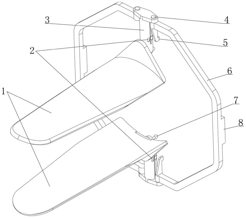
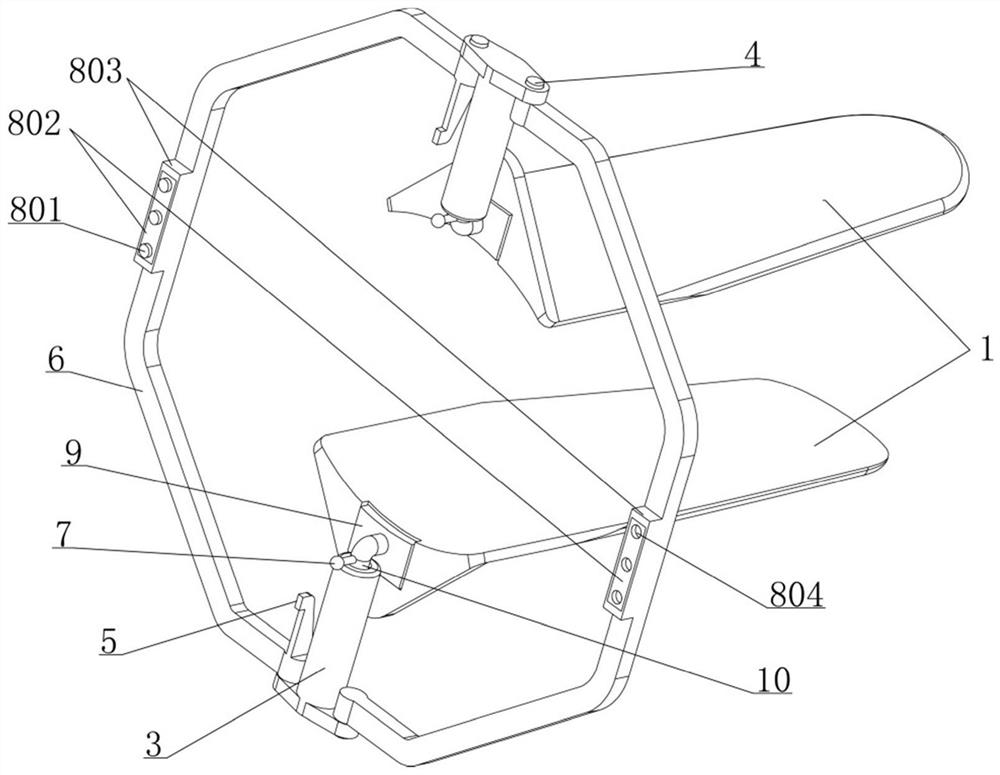
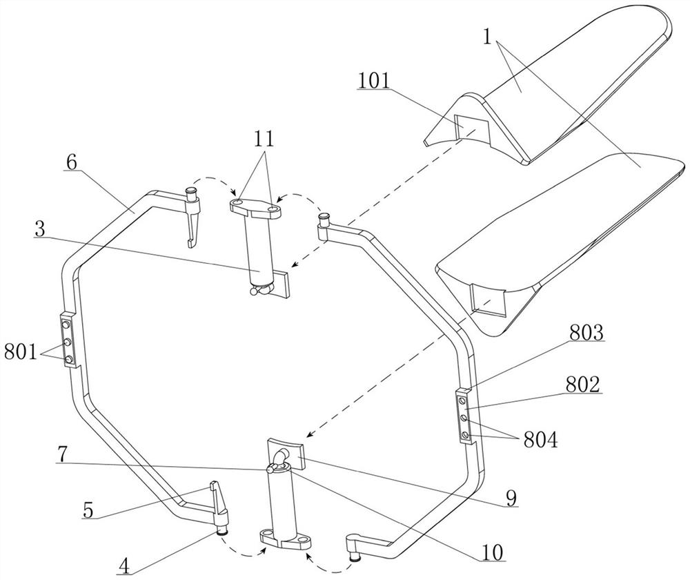
[0027] see Figure 1-8 As shown, the present invention discloses a vaginal dilator for gynecology, which includes two handles 6 and two placement cylinders 3; the shapes of the two handles 6 are consistent and both are arcuate, and the upper and lower ends of each handle 6 are Each is provided with a hinged portion 4; the hinged portion 4 at the upper end of the two handles 6 is respectively connected with the upper end of a placement cylinder 3 in two places, and the hinged portion 4 at the lower end of the two handles 6 is respectively connected with the lower end of the other placement cylinder 3 at two places Rotationally connected, under the support of the two handles 6, the two placement cylinders 3 are distributed at intervals up and down and the relative positions of the two are constant; Can be rotated relative to the two placement cylinders 3; a locking mechanism 8 is provided between the two handles 6. When the two handles 6 are rotated to the right rear of the two ...

Embodiment 2

[0047] On the basis of the structure of the gynecological vaginal dilator disclosed in the embodiment 1, this embodiment has further improvements to the combination of the combination seat 9 and the expansion sheet 1, and the specific structure is:

[0048] see Figure 11 , 12 , 13, the opposite ends of the two core rods 10 are provided with a transverse arm 17 extending vertically forward, and the combined seat 9 is in the shape of a rectangular plate and is vertically and fixedly connected with the front end of the transverse arm 17; The rear end of the expansion sheet 1 is provided with an integral and vertical guard plate 102, and the rear end surface of the guard plate 102 is provided with a square groove 103 for accommodating the combination seat 9; one side of the square groove 103 is provided for limiting the combination seat. 9. The rib 104 that moves outward, and the other side opposite to the rib 104 is provided with an elastically oscillating claws 105, and the cl...

Embodiment 3

[0052] see figure 2 , 5 , 8, in the vaginal dilator for gynecology disclosed in the foregoing embodiment, it does not have an expansion degree adjustment mechanism, and the expansion degree will not continue to increase only when the two push springs 15 are balanced by force, although this working mode It has significant advantages and can be applied to different patients with large individual differences, but it also has certain shortcomings in clinical use; in clinical, different clinical operations such as examinations or operations have different requirements for the degree of vaginal dilation, When a small degree of expansion can meet the needs of clinical operations, it is obviously useless to continue to increase the degree of expansion because the force of the two push springs 15 has not yet reached a balance. It will cause unnecessary pain and injury to the patient. In order to solve the above-mentioned technical problem, the present embodiment also has the followi...


PUM


Abstract

The invention relates to the field of medical devices, and specifically discloses a vaginal dilator for gynecology, which comprises two handles with hinged parts on both upper and lower ends; the upper ends of the two handles are respectively rotatably connected with a placement cylinder, and the lower ends of the two handles are respectively connected with another handle. A placement cylinder is rotatably connected; each of the two placement cylinders defines a core rod and a push spring; the opposite ends of the two core rods are each connected with a combination seat, and the two combination seats are respectively combined with expansion pieces; each of the placement cylinders is provided with a non-return mechanism And a station slot, a handle is fixed with two limit blocks, when the handle is rotated to the rear of the two placement cylinders, the two limit blocks just enter into the two station slots respectively, at this time, the non-return mechanism allows the two core rods to move toward each other. The middle is close to prevent the two core rods from moving away. This gynecological vaginal dilator is based on the exquisite structural design, which is convenient and quick to use, with balanced expansion force and sufficient expansion space.

Description

technical field [0001] The invention relates to a medical instrument, in particular to a vaginal dilator used in gynecological clinical examination and treatment. Background technique [0002] Vaginal dilator, also known as vaginal dilator, is often used to dilate the vagina in routine examination and surgical treatment of gynecological diseases to obtain a better inspection field or surgical field. It is a commonly used medical device in gynecology. The expansion wing and the handle are formed, the two expansion wings are duckbill-shaped and the rear ends are hinged, the handle is arranged at the rear end of the two expansion wings, the opening angle of the two expansion wings can be adjusted by the handle, and the position of the two expansion wings can be locked. This achieves the intended expansion purpose. Since most of the existing vaginal dilators adjust the degree of expansion by adjusting the opening angle, during clinical use, the degree of expansion applied by th...

Claims


Application Information

Patent Timeline
Patent Type & Authority Patents(China)
IPC IPC(8): A61B1/32A61B1/303A61M29/00
CPCA61B1/32A61B1/303A61M29/00
Inventor 王力冯晓军刘秀平黄付荣
Owner 山东中医药大学第二附属医院(山东省中西医结合医院)
Learn More