Electric clothes hanger with stall protection function
A technology of protection function and drying rack, applied in the field of Internet of Things, can solve problems such as speed out of control, and achieve the effect of avoiding speed out of control
- Summary
- Abstract
- Description
- Claims
- Application Information
AI Technical Summary
Problems solved by technology
Method used
Image
Examples
Embodiment 1
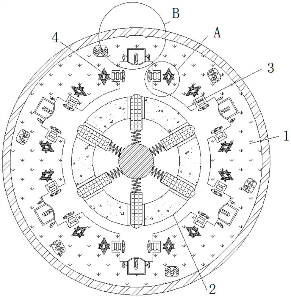
[0026] see figure 1 with figure 2 , an electric drying rack with a stall protection function, comprising a housing 1, a stop assembly 2 is movably connected to the middle of the inner wall of the housing 1, and a movable groove 3 is fixedly connected to the inner wall of the housing 1 and the outer side close to the stop assembly 2 , the inner wall of the housing 1 is provided with a fixed groove 4 near the outer side of the movable groove 3, the inner side of the inner wall of the fixed groove 4 is fixedly connected with the clamping assembly 5, and the outer side of the inner wall of the fixed groove 4 is fixedly connected with the movable assembly 6;
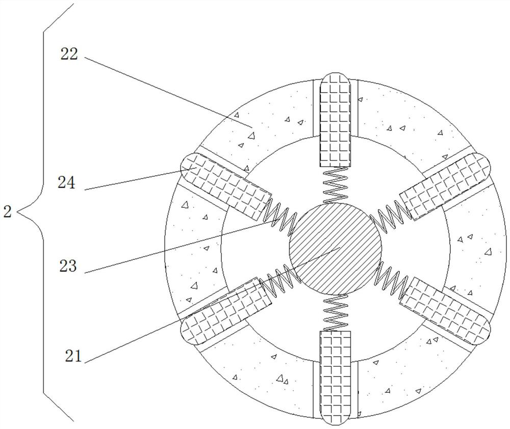
[0027] The stop assembly 2 includes a rotating shaft 21, the outer side of the rotating shaft 21 is fixedly connected with a movable sleeve 22, the outer side of the rotating shaft 21 is fixedly connected with a spring 23, and the outer side of the spring 23 is fixedly connected with a fixed block 24 which penetrates and ext...
Embodiment 2
[0029] see figure 1 with image 3 , an electric drying rack with a stall protection function, comprising a housing 1, a stop assembly 2 is movably connected to the middle of the inner wall of the housing 1, and a movable groove 3 is fixedly connected to the inner wall of the housing 1 and the outer side close to the stop assembly 2 , the inner wall of the housing 1 is provided with a fixed groove 4 near the outer side of the movable groove 3, the inner side of the inner wall of the fixed groove 4 is fixedly connected with the clamping assembly 5, and the outer side of the inner wall of the fixed groove 4 is fixedly connected with the movable assembly 6;
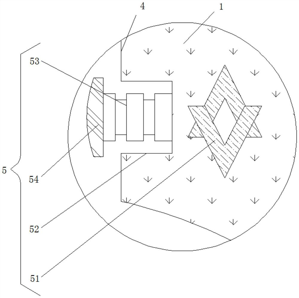
[0030] Clamping assembly 5 comprises electromagnet 51 and groove 52, and the inner side of groove 52 inner wall is fixedly connected with magnetostrictive rod 53, and magnetostrictive rod 53 can elongate under the influence of magnetic field, and the inner side of magnetostrictive rod 53 is fixed Connected with a clamping bl...
Embodiment 3
[0032] see figure 1 with Figure 4 , an electric drying rack with a stall protection function, comprising a housing 1, a stop assembly 2 is movably connected to the middle of the inner wall of the housing 1, and a movable groove 3 is fixedly connected to the inner wall of the housing 1 and the outer side close to the stop assembly 2 , the inner wall of the housing 1 is provided with a fixed groove 4 near the outer side of the movable groove 3, the inner side of the inner wall of the fixed groove 4 is fixedly connected with the clamping assembly 5, and the outer side of the inner wall of the fixed groove 4 is fixedly connected with the movable assembly 6;
[0033] The movable assembly 6 includes a piezoresistor 61, a positive plate 62, a negative plate 63 and a support 64. The bottom of the support 64 is fixedly connected with a shrapnel 65, the top of the shrapnel 65 is fixedly connected with a movable block 66, and the inner wall of the movable block 66 is fixedly connected w...
PUM
 Abstract
Description
Claims
Application Information
 - R&D
- Intellectual Property
- Life Sciences
- Materials
- Tech Scout
- Unparalleled Data Quality
- Higher Quality Content
- 60% Fewer Hallucinations
Browse by: Latest US Patents, China's latest patents, Technical Efficacy Thesaurus, Application Domain, Technology Topic, Popular Technical Reports.
© 2025 PatSnap. All rights reserved.Legal|Privacy policy|Modern Slavery Act Transparency Statement|Sitemap|About US| Contact US: help@patsnap.com


