
Heat dissipation structure, electric appliance box and outdoor unit

A technology of heat dissipation structure and electrical box

Pending Publication Date: 2021-09-10
GREE ELECTRIC APPLIANCES INC
View PDF0 Cites 0 Cited by
  • Summary
  • Abstract
  • Description
  • Claims
  • Application Information

AI Technical Summary

Problems solved by technology

[0004] The purpose of the present invention is to provide a heat dissipation structure, an electrical box and an outdoor unit, so as to solve the technical problem of the poor heat dissipation effect of the electrical box in the prior art

Method used


Image

  • Heat dissipation structure, electric appliance box and outdoor unit
  • Heat dissipation structure, electric appliance box and outdoor unit
  • Heat dissipation structure, electric appliance box and outdoor unit

Examples


Embodiment 1

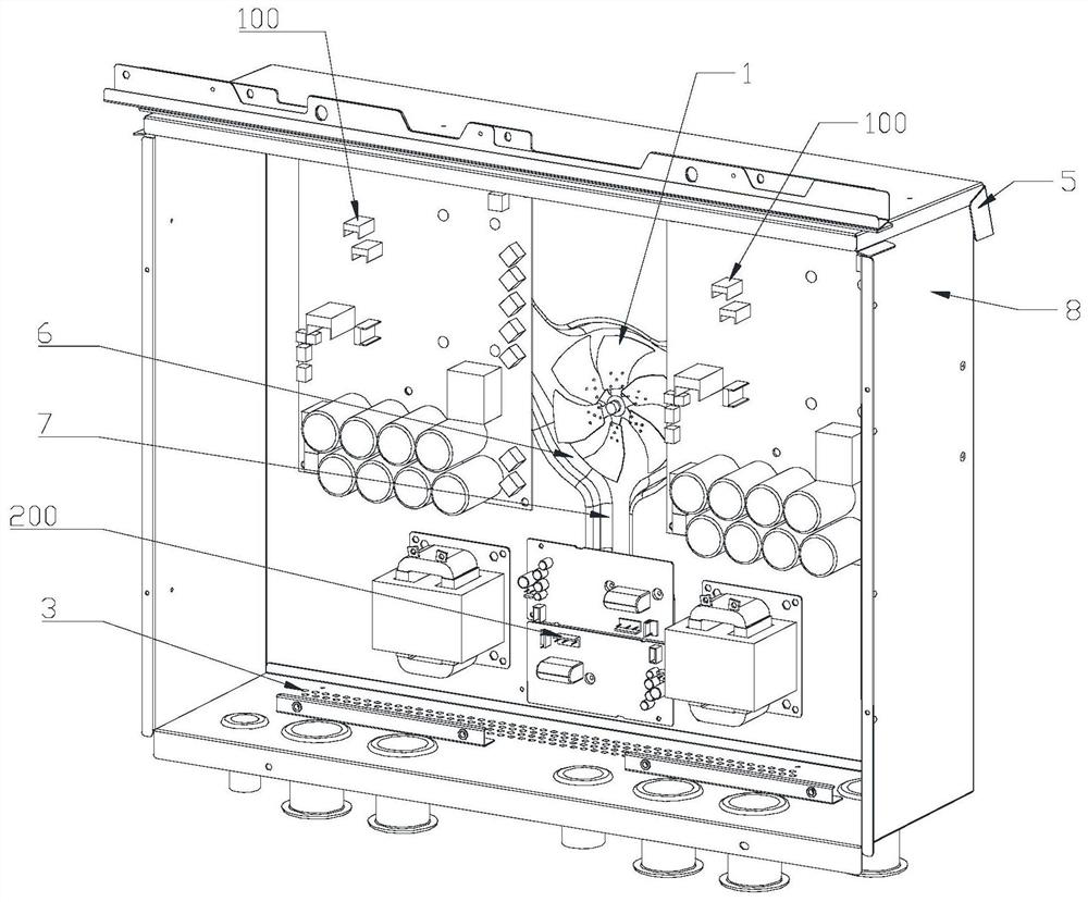
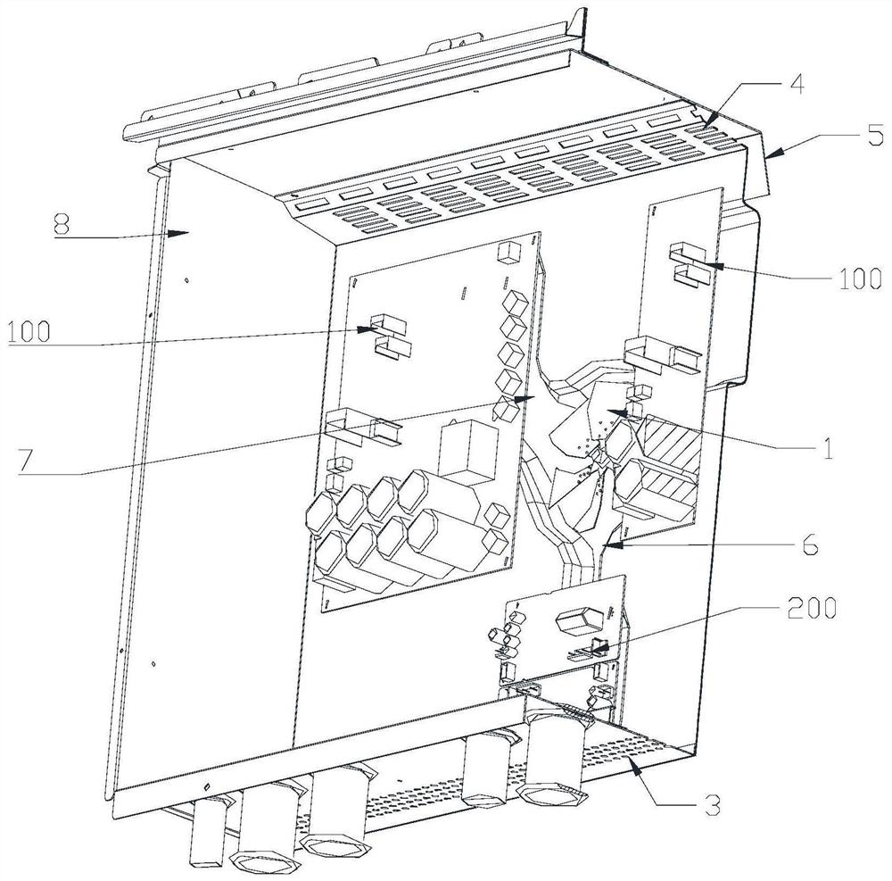
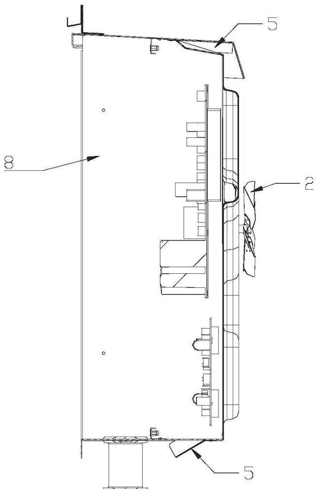
[0029] Such as figure 1 with image 3 As shown, the present invention provides a heat dissipation structure, including a first heat dissipation blade 1 and a second heat dissipation blade 2 respectively arranged inside and outside the electrical box; the second heat dissipation blade 2 is a passive drive structure, and A cooling fan blade 1 is arranged coaxially, and can drive the first cooling fan blade 1 to follow and rotate synchronously.

[0030] It should be noted here that the passive driving referred to herein refers to the driving mode in which the second cooling fan 2 does not require an external power supply.

[0031] Specifically, there are heating elements inside the electrical box, such as the compressor driving board 100 and the fan driving board 200. In order to improve the service life of the equipment, the heating elements are respectively radiated inside and outside the electrical box, thereby improving the heat dissipation effect, and The fan blade cooling...

Embodiment 2

[0033] Such as figure 1 with image 3 As shown, the present invention provides a heat dissipation structure, including a first heat dissipation blade 1 and a second heat dissipation blade 2 respectively arranged inside and outside the electrical box; the second heat dissipation blade 2 is a passive drive structure, and A cooling fan blade 1 is arranged coaxially, and can drive the first cooling fan blade 1 to follow and rotate synchronously.

[0034] It should be noted here that the passive driving referred to herein refers to the driving mode in which the second cooling fan 2 does not require an external power supply.

[0035] Specifically, there are heating elements inside the electrical box, such as the compressor driving board 100 and the fan driving board 200. In order to improve the service life of the equipment, the heating elements are respectively radiated inside and outside the electrical box, thereby improving the heat dissipation effect, and The fan blade heat di...

Embodiment 3

[0040] Such as figure 1 with image 3 As shown, the present invention provides a heat dissipation structure, including a first heat dissipation blade 1 and a second heat dissipation blade 2 respectively arranged inside and outside the electrical box; the second heat dissipation blade 2 is a passive drive structure, and A cooling fan blade 1 is arranged coaxially, and can drive the first cooling fan blade 1 to follow and rotate synchronously.

[0041] It should be noted here that the passive driving referred to herein refers to the driving mode in which the second cooling fan 2 does not require an external power supply.

[0042]Specifically, there are heating elements inside the electrical box, such as the compressor driving board 100 and the fan driving board 200. In order to improve the service life of the equipment, the heating elements are respectively radiated inside and outside the electrical box, thereby improving the heat dissipation effect, and The fan blade cooling ...


PUM


Abstract

The invention provides a heat dissipation structure, an electric appliance box and an outdoor unit, relates to the technical field of air conditioners, and solves the technical problem of poor heat dissipation effect of the electric appliance box. The heat dissipation structure comprises a first heat dissipation fan blade and a second heat dissipation fan blade which are respectively arranged inside and outside the electric appliance box, wherein the second heat dissipation fan blade is of a passive driving structure, is coaxially arranged with the first heat dissipation fan blade and can drive the first heat dissipation fan blade to synchronously rotate along with the first heat dissipation fan blade; and a third heat dissipation assembly and a fourth heat dissipation assembly are arranged in the electric appliance box. The heat dissipation structure is used for heat dissipation of the electric appliance box, external fan blades in the heat dissipation structure are driven to rotate through drainage inlet air or blowing air generated when a fan in the outdoor unit runs, the external fan blades rotate to drive built-in power-supply-free fan blades to rotate, and a power supply does not need to be consumed; and when the outdoor unit is started, heat dissipation work is started, and when the outdoor unit is stopped, heat dissipation work is stopped, so that the heat dissipation structure is energy-saving and environmentally-friendly.

Description

technical field [0001] The invention relates to the technical field of air conditioners, in particular to a heat dissipation structure, an electrical box and an outdoor unit. Background technique [0002] In the air-conditioning industry, the temperature inside the electrical box will affect the life of the electronic components inside the electrical box. Optimizing the heat dissipation of the electrical box has always been a difficult point in the industry. The traditional electrical box structure only dissipates heat by opening windows, without considering the air flow, and the heat dissipation effect is poor. [0003] In order to improve the heat dissipation effect, the commonly used heat dissipation schemes include refrigerant heat dissipation, radiator heat dissipation, and built-in power supply small fan heat dissipation; the refrigerant heat dissipation scheme is to set the copper tube in the aluminum plate, and the refrigerant flows through the copper tube through th...

Claims


Application Information

Patent Timeline
IPC IPC(8): F24F1/24
CPCF24F1/24
Inventor 吴梅彬袁国炉周琪张红梅陈雪
Owner GREE ELECTRIC APPLIANCES INC
Learn More