Universal mechanical testing machine
A mechanical testing machine, a universal technology, applied in the field of mechanical testing, can solve problems such as incapable of top pressure testing
- Summary
- Abstract
- Description
- Claims
- Application Information
AI Technical Summary
Problems solved by technology
Method used
Image
Examples
Embodiment 1
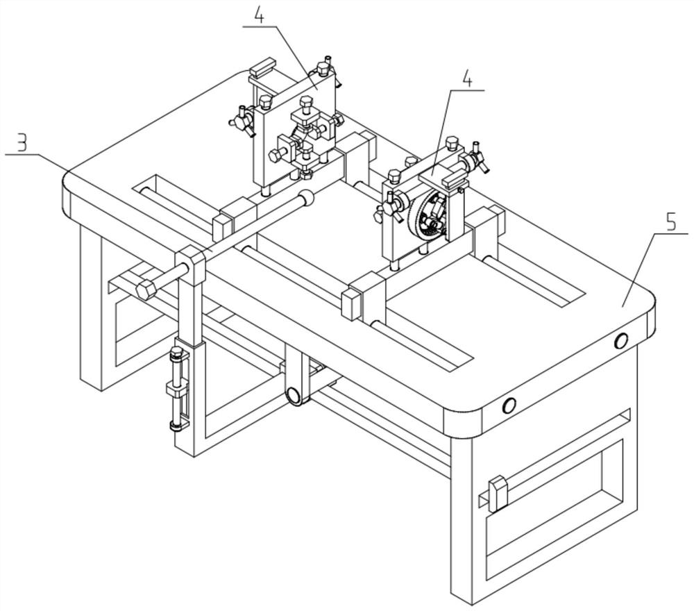
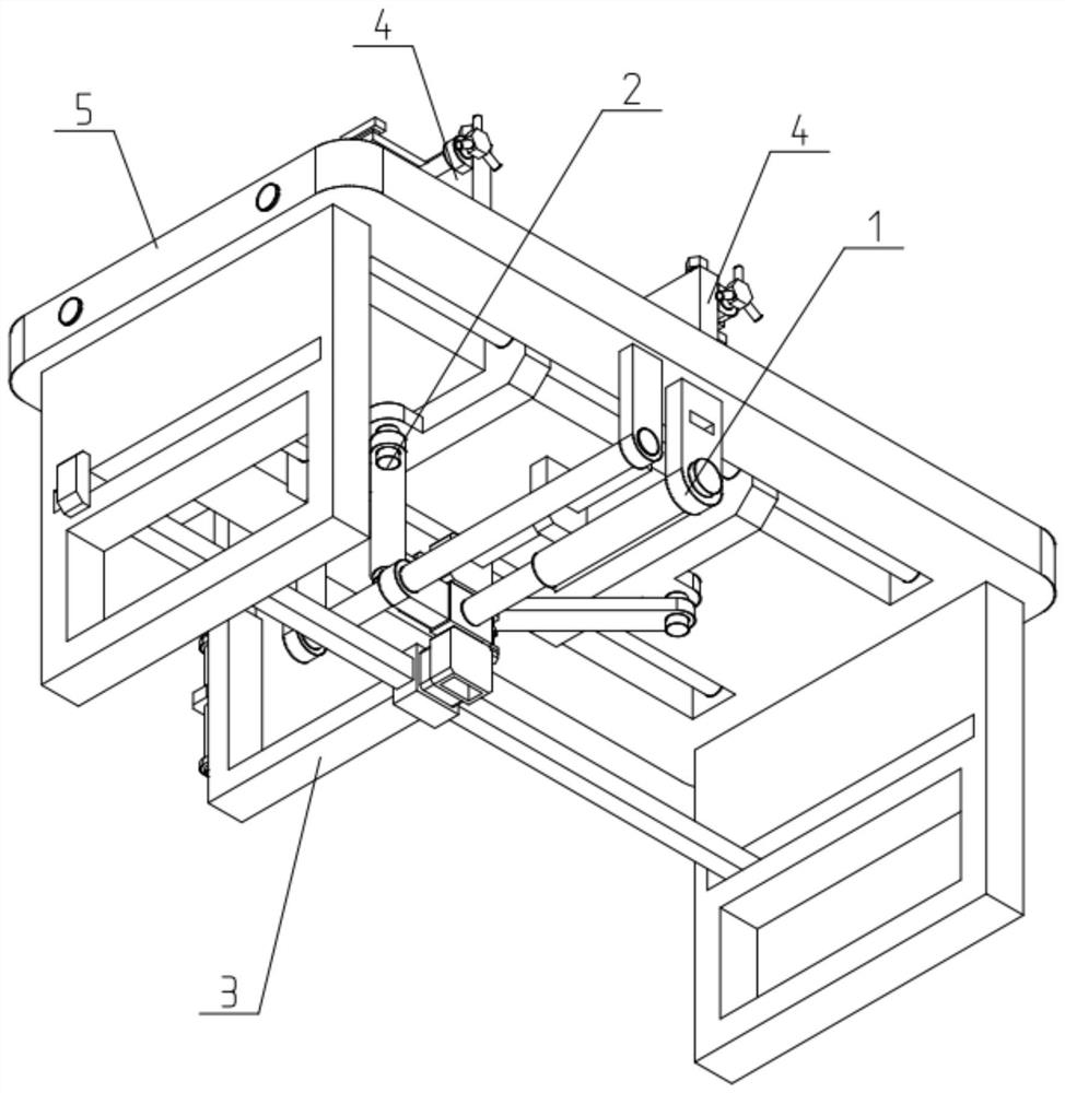
[0039] Such as Figure 1-12 As shown, a universal mechanical testing machine includes a driving part 1, a tension-compression transmission part 2, a lateral pressure transmission part 3, a clamping part 4 and a frame 5, and the driving part 1 is mated and connected to the bottom of the frame 5 the middle of the drive part 1; the drive part 1 is connected to the pull-press drive part 2 or the side-press drive part 3; Clamping part 4; the two ends of the lateral pressure transmission part 3 are slidably fitted on the frame 5, and the two ends are matched between the two clamping parts 4, so as to be clamped and fixed between the two clamping parts 4. The test piece between the two clamping parts 4 is subjected to side pressing.
[0040] A universal mechanical testing machine of the present invention can be used for tensile test or compression test of materials, and can also carry out top pressure test from the side of the material, and can test the compression resistance of the...
Embodiment 2
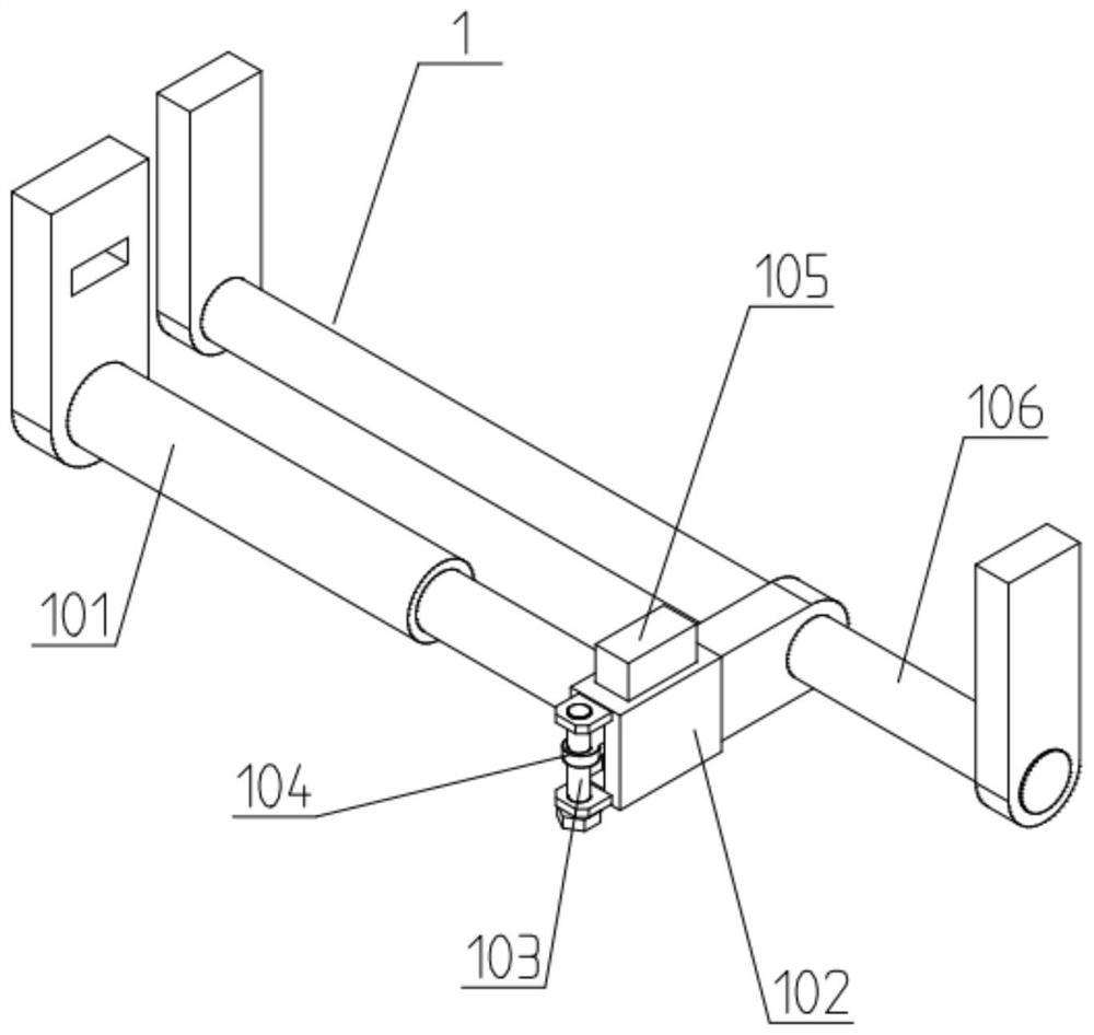
[0042] Such as Figure 1-12 As shown, the drive unit 1 includes an electric push rod 101, a push-pull frame 102, a first screw 103, a first slider 104, a sliding plate 105 and a guide shaft 106; the fixed end of the electric push rod 101 is pushed through The rod seat is fixed on the frame 5; the movable end of the electric push rod 101 is fixedly connected to the push-pull frame 102; It is fixed on the frame 5 by bearing brackets; the upper and lower ends of the first screw rod 103 are rotated and fitted on the upper and lower ends of one side of the push-pull frame 102, and the middle threaded transmission of the first screw rod 103 is slidably fitted in the push-pull frame. The first slider 104 in the side slideway of the frame 102, the inner side of the first slider 104 is fixedly connected and slidably fitted with the sliding board 105 in the longitudinal slideway of the push-pull frame 102; The pull-press drive part 2 or the side-press drive part 3 are plugged in and dr...
Embodiment 3
[0045] Such as Figure 1-12 As shown, the pull-press transmission part 2 includes a first socket socket 201, a first pressure sensor 202, a movable seat 203, a pull-press connecting rod 204, a guide cross plate 205 and a limit sliding sleeve 206; The socket 201 is fixed on the inside of the first pressure sensor 202, and the outside of the first pressure sensor 202 is fixedly connected to the movable seat 203; Cooperating first slot; the inner end of the first socket 201 is fixedly connected to one end of the guide horizontal plate 205, and the middle part of the guide horizontal plate 205 slides and fits in the horizontal chute of the limit sliding sleeve 206, and the limit The sliding sleeve 206 is fixed on the frame 5; the two ends of the movable seat 203 are respectively rotatably connected to the inner end of a pull-press link 204; part 4 to drive the two clamping parts 4 to slide toward each other or away from each other on the frame 5 . After the material to be tested...
PUM
 Abstract
Description
Claims
Application Information
 - R&D
- Intellectual Property
- Life Sciences
- Materials
- Tech Scout
- Unparalleled Data Quality
- Higher Quality Content
- 60% Fewer Hallucinations
Browse by: Latest US Patents, China's latest patents, Technical Efficacy Thesaurus, Application Domain, Technology Topic, Popular Technical Reports.
© 2025 PatSnap. All rights reserved.Legal|Privacy policy|Modern Slavery Act Transparency Statement|Sitemap|About US| Contact US: help@patsnap.com


