Laser projection equipment

A technology of laser projection and equipment, applied in the field of projection display, can solve the problems of poor image display effect of laser projection equipment, permanent damage of laser, etc.

Active Publication Date: 2021-09-10
QINGDAO HISENSE LASER DISPLAY CO LTD
View PDF6 Cites 0 Cited by
  • Summary
  • Abstract
  • Description
  • Claims
  • Application Information

AI Technical Summary

Problems solved by technology

[0004] The embodiment of the present disclosure provides a laser projection device, which can solve the problems in the related art that the long-term COD failure of the laser causes permanent damage to the laser, and the image display effect of the laser projection device is poor.

Method used


Image

  • Laser projection equipment
  • Laser projection equipment
  • Laser projection equipment

Examples


Embodiment Construction

[0024] In order to make the purpose, technical solution and advantages of the present disclosure clearer, the implementation manners of the present disclosure will be further described in detail below in conjunction with the accompanying drawings.

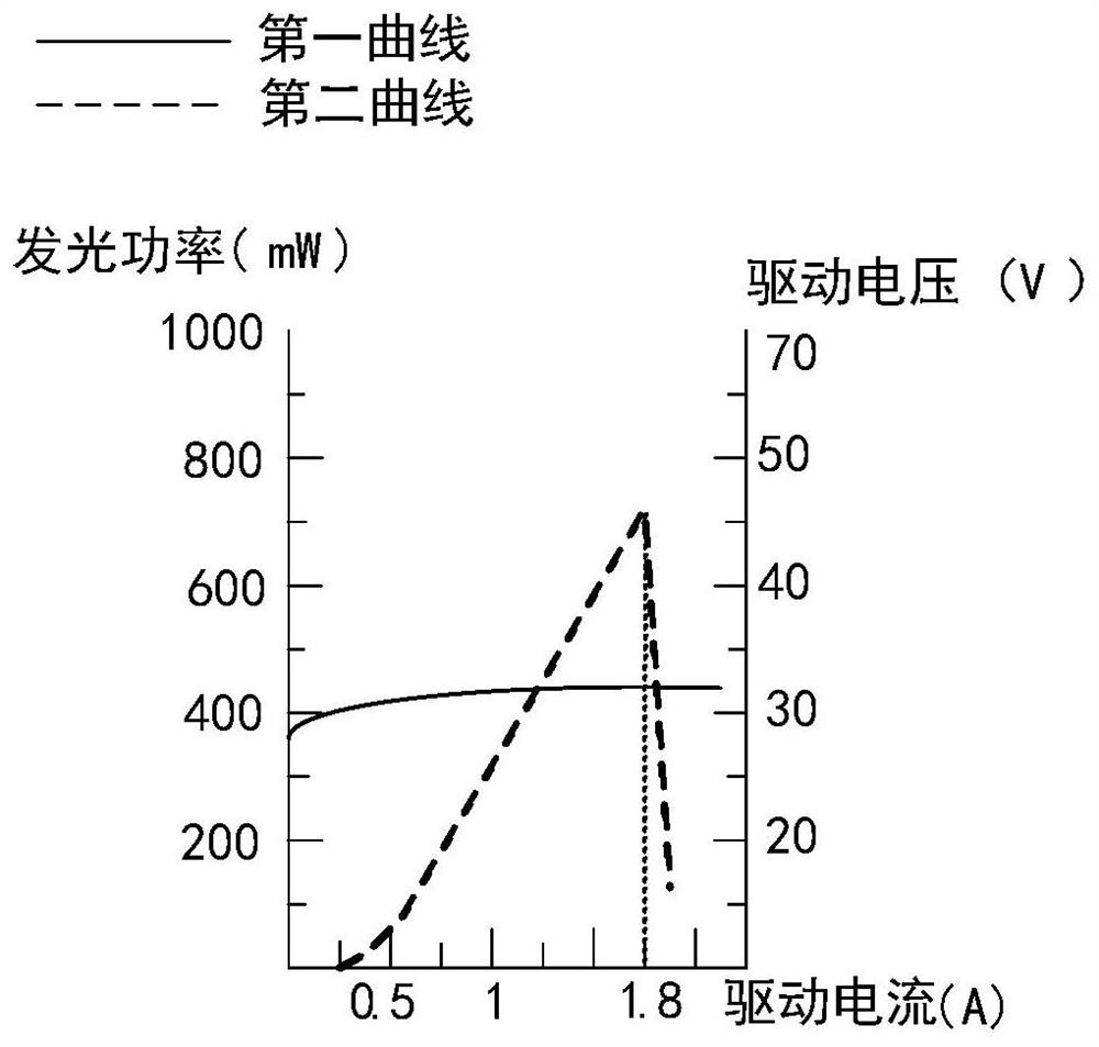
[0025] figure 1 It is a schematic diagram of the output characteristics of a laser when a COD fault occurs in the laser provided by the related art. The schematic diagram includes a first curve and a second curve, the first curve is a variation curve of the driving voltage of the laser, and the second curve is a variation curve of the driving current of the laser. The abscissa in the schematic diagram is the driving current, the first ordinate is the luminous power of the laser, and the second ordinate is the driving voltage of the laser. Wherein, the unit of driving current is ampere (A), the unit of luminous power is milliwatt (mW), and the unit of driving voltage is volt (V).

[0026] refer to figure 1 1. During the working p...


PUM


Abstract

The invention discloses laser projection equipment, and belongs to the field of projection display. According to the laser projection equipment, at least one brightness sensor is arranged in the light emitting side of a laser light source, and each brightness sensor is connected with a display control circuit and used for detecting a first brightness value of a set of lasers and sending the first brightness value to the display control circuit; the laser projection equipment comprises a display control circuit; the display control circuit is used for acquiring a second brightness value corresponding to the driving current of each group of lasers, and when the difference value between the second brightness value of the laser and the first brightness value of the laser in a target time length is greater than a difference value threshold value, adjusting a current control signal of a laser driving assembly corresponding to the laser until the difference value is smaller than or equal to the difference value threshold. According to the laser projection equipment provided by the invention, the COD fault of the laser can be eliminated in time, so that the duration of the COD fault of the laser is reduced, the damage rate of the laser is reduced, and the image display effect of the laser projection equipment is ensured.

Description

technical field [0001] The present disclosure relates to the field of projection display, in particular to a laser projection device. Background technique [0002] Presently, laser projection devices may include a laser light source, which may include lasers of at least one color. For example, if the laser projection device is a monochromatic laser projection device, the laser light source may include a blue laser for emitting blue laser light. If the laser projection device is a full-color laser projection device, the laser light source may include a blue laser, a red laser for emitting red laser light, and a green laser for emitting green laser light. [0003] In the related art, when the laser in the laser projection equipment emits laser light, because the semiconductor junction of the laser exceeds the power density and causes overload, the cavity surface of the laser needs to withstand a large optical power density to melt and recrystallize, making the cavity of the l...

Claims


Application Information

Patent Timeline
Patent Type & Authority Applications(China)
IPC IPC(8): G03B21/20
CPCG03B21/2013G03B21/204G03B21/2053G03B21/20
Inventor 崔荣荣曹利明
Owner QINGDAO HISENSE LASER DISPLAY CO LTD
Why Eureka
Try Eureka