
Wire clamping device and winding machine

A wire clamping and winding technology, which is applied in coil manufacturing and other directions, can solve problems such as enameled wire stuck, equipment failure, and difficult to control the gap between the wire sleeve and the wire post.

Pending Publication Date: 2021-09-10
XIAMEN HONGFA IND ROBOT CO LTD
View PDF0 Cites 0 Cited by
  • Summary
  • Abstract
  • Description
  • Claims
  • Application Information

AI Technical Summary

Problems solved by technology

The wire winding post is to wind the enameled wire on a mechanical post. The mechanical post is usually round. The enameled wire must be wound many times to fix it on the winding post, which will increase the cost of the enameled wire. The off-line sleeve needs a large power to complete the off-line
In addition, it is difficult to control the gap between the wire-off sleeve and the wire-off column. If the gap is too small, the wire is easily stuck; if the gap is too large, when the enameled wire diameter is small, the enameled wire is easy to get stuck in the gap, causing equipment failure.
The wire clamping mechanism generally clamps the enameled wire by opening and closing left and right or up and down. The wire clamping mechanism is usually realized by a linkage mechanism, and the clamping power cannot be increased, which may easily cause the situation that the equipment cannot clamp thick wires

Method used


Image

  • Wire clamping device and winding machine
  • Wire clamping device and winding machine
  • Wire clamping device and winding machine

Examples


Embodiment Construction

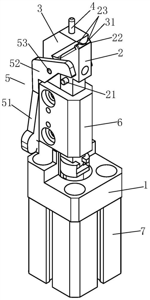
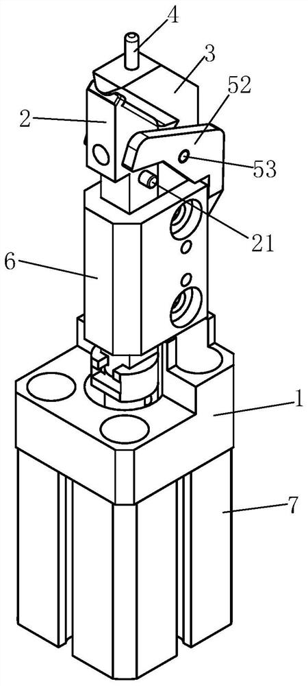
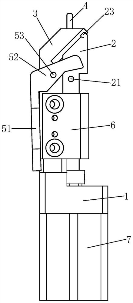
[0027] Examples, see Figure 1-Figure 5 As shown, a wire clamping device of the present invention includes a mounting base 1, a wire clamp and a driving mechanism. The wire clamp includes a movable clamping finger 2 and a fixed clamping finger 3 arranged on the mounting base 1. and connect the movable clamp finger 2 to drive the movable clamp finger 2 to close or separate from the fixed clamp finger 3; it also includes a winding column 4, which is arranged on the movable clamp finger 2, and the winding column 4 Through the fixed clip finger 3, as the movable clip finger 2 and the fixed clip finger 3 are closed, the winding part of the winding column 4 is exposed outside the fixed clip finger 3, and as the movable clip finger 2 and the fixed clip finger 3 are separated, The thread winding part of the thread winding post 4 is in an off-line state received in the fixed finger 3, so that there is no need to use an off-line mechanism to assist in off-line. The thread winding part ...


PUM


Abstract

The invention discloses a wire clamping device and a winding machine. The wire clamping device comprises a mounting seat, a wire clamp and a driving mechanism, wherein the wire clamp comprises a movable clamping finger and a fixed clamping finger arranged on the mounting seat, the driving mechanism is arranged on the mounting seat and is connected with the movable clamping finger to drive the movable clamping finger and the fixed clamping finger to be closed or separated, the wire clamping device further comprises a wire winding column, the wire winding column is arranged on the movable clamping finger, the wire winding column penetrates through the fixed clamping finger, the wire winding part of the wire winding column is exposed out of the fixed clamping finger along with closing of the movable clamping finger and the fixed clamping finger, and the wire winding part of the wire winding column is in a wire loosening state of being contained in the fixed clamping finger along with separation of the movable clamping finger and the fixed clamping finger. According to the invention, a wire clamping mode and a wire winding column mode can be realized on the same mechanism, and the wire clamping mode and the wire winding column mode can be combined for use, so that the wire clamping device can be well used no matter an enameled wire with a small wire diameter or an enameled wire with a large wire diameter.

Description

technical field [0001] The invention relates to the technical field of mechanical equipment, in particular to a wire clamping device and a wire winding machine. Background technique [0002] A winding machine is a machine that winds a wire-like object onto a specific workpiece. Most products that require enameled wire to be wound into an inductance coil require a winding machine. Fixing one end of the wire end is an essential step in the winding process of the winding machine, which is usually achieved by a winding post or a clamping mechanism. The wire winding post is to wind the enameled wire on a mechanical post. The mechanical post is usually round. The enameled wire must be wound many times to fix it on the winding post, which will increase the cost of the enameled wire. The off-line sleeve needs a large power to complete the off-line. In addition, it is difficult to control the gap between the stripping sleeve and the stripping column. If the gap is too small, the st...

Claims


Application Information

Patent Timeline
Patent Type & Authority Applications(China)
IPC IPC(8): H01F41/06
CPCH01F41/06
Inventor 廖建明白杰昌
Owner XIAMEN HONGFA IND ROBOT CO LTD
Learn More