Power bus duct

A busway and power technology, applied in the field of power busway and power transmission, can solve the problems of submersion, immersion, penetration, etc.

Inactive Publication Date: 2021-09-10
杨贞和
View PDF0 Cites 2 Cited by
  • Summary
  • Abstract
  • Description
  • Claims
  • Application Information

AI Technical Summary

Problems solved by technology

[0004] To sum up, the present invention provides a power busway, which is used to solve the problem that when the existing power busway is installed

Method used


Image

  • Power bus duct
  • Power bus duct
  • Power bus duct

Examples


Embodiment Construction

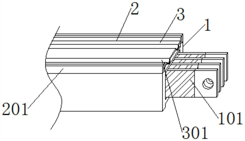
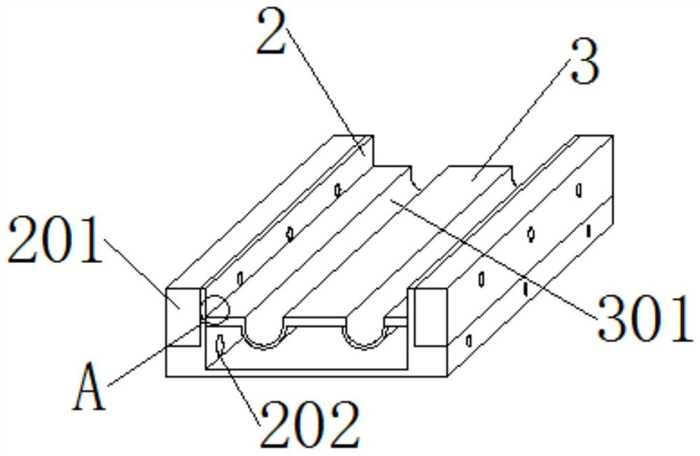
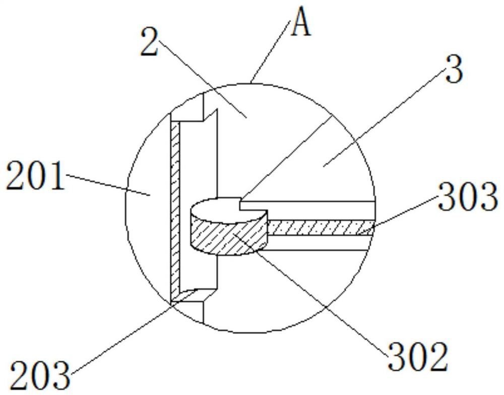
[0024] Please refer to Figure 1 to Figure 6 middle:

[0025] A power busway, comprising: a main body 1, the two ends of the main body 1 are connected with a plug-in block 101, the surrounding of the main body 1 is connected with a protective shell 2, the two sides of the top of the protective shell 2 are connected with extension blocks 201, and the middle part of the top of the protective shell 2 is connected with The pressure plate 3 and the protective shell 2 include an extension block 201, a suction shaft 202 and a lifting groove 203. The extension block 201 is a rectangular block fitted in grooves on both sides of the top of the protective shell 2, and the suction shaft 202 is The middle part of the top of the protective shell 2 is fitted with a circular shaft close to the two sides of the top. The lifting groove 203 is a rectangular groove with an arc-shaped inner wall on both sides of the central part of the top of the protective shell 2. The extension block 201 include...


PUM


Abstract

A power bus duct comprises a main body, a plug block, a protective shell, extension blocks and a pressure plate, the plug block is embedded in one end of the main body, the protective shell is connected to the periphery of the main body, the extension blocks are embedded in the two sides of the top end of the protective shell, and the pressure plate is embedded in the middle of the top end of the protective shell. According to the device, the extending blocks can extend when water submerges the main body protective shell, so that a discharge hole is blocked, and when the water does not flow to the protective shell, the protection area of the device can be increased to prevent the water from submerging the main body protective shell to influence the main body.

Description

technical field [0001] The present invention relates to the technical field of power transmission, and more specifically, to the technical field of a power busway. Background technique [0002] Power transmission refers to the transmission of power in daily life through various equipment and cables in the city to meet the needs of various electrical appliances in daily life, and the power busway refers to the use of different cables It is a device for power transmission in the form of cables, which is used to distribute the power transmission of relatively large power equipment whose cables are difficult to load. It is also the main equipment for cable transmission used by some existing fixed large equipment, but the existing bus duct is It has been installed on the ground for a long time, so when the busway installed outdoors is in an area with excessive rainfall, the busway shell will not be able to drain the water from the surface in time, so the busway will be soaked to ...

Claims


Application Information

Patent Timeline
IPC IPC(8): H02G5/06
CPCH02G5/06
Inventor 杨贞和
Owner 杨贞和
Why Eureka
Try Eureka