Food sterilization device

A technology for sterilization equipment and food, which is applied in the field of food processing, and can solve the problems of height adjustment of racks and inability to use racks, etc.

Inactive Publication Date: 2021-09-14
徐州凯佳食品有限公司
View PDF0 Cites 0 Cited by
  • Summary
  • Abstract
  • Description
  • Claims
  • Application Information

AI Technical Summary

Problems solved by technology

[0004] In order to make up for the deficiencies of the existing technology and solve the problem that the existing ultraviolet food sterilization equipment does not have the function of adjusting the height of the shelf in the sterilization chamber, resulting in the staff not being able to make full use of the space of the shelf for different volumes of food, The invention proposes a food sterilization equipment

Method used


Image

  • Food sterilization device
  • Food sterilization device
  • Food sterilization device

Examples


Embodiment 1

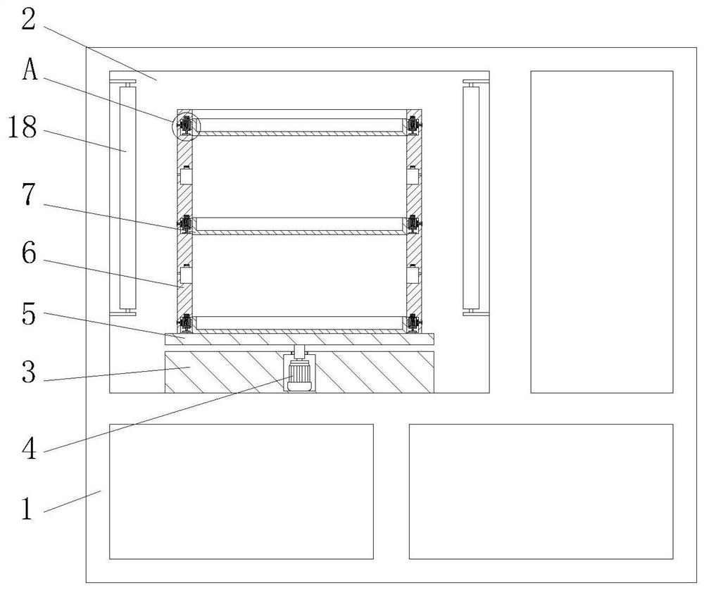
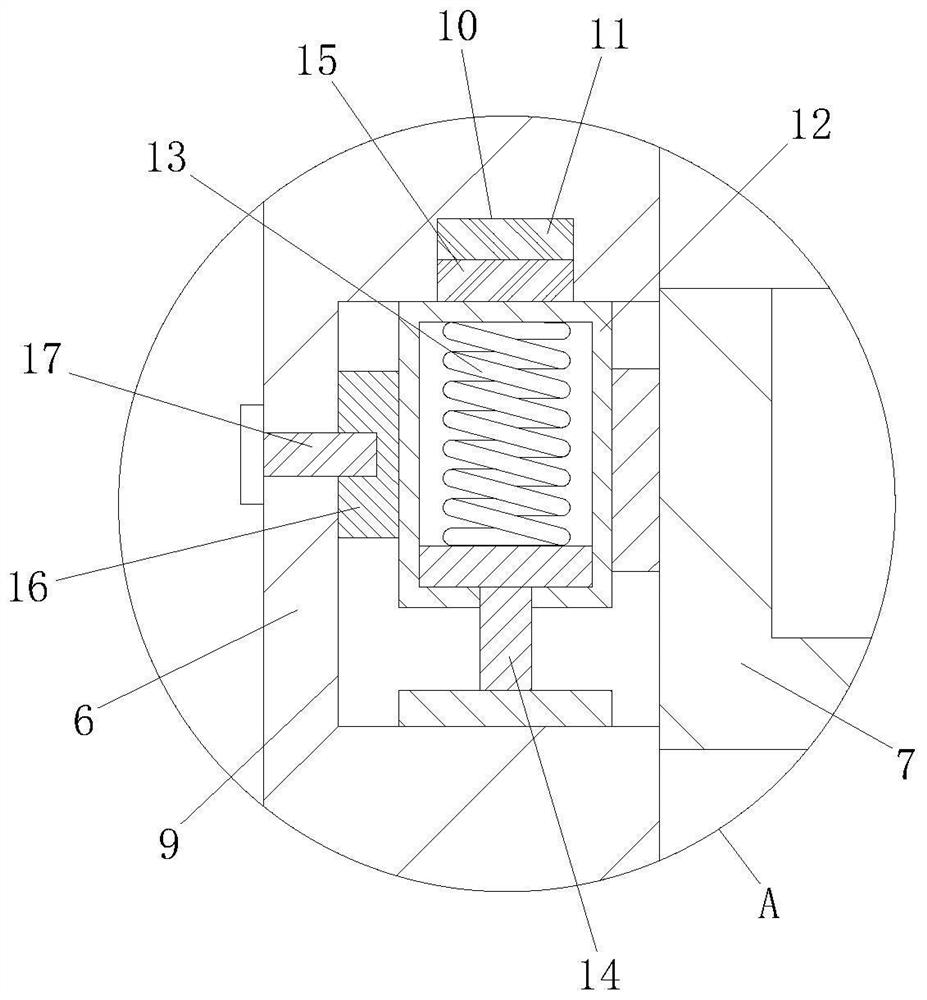
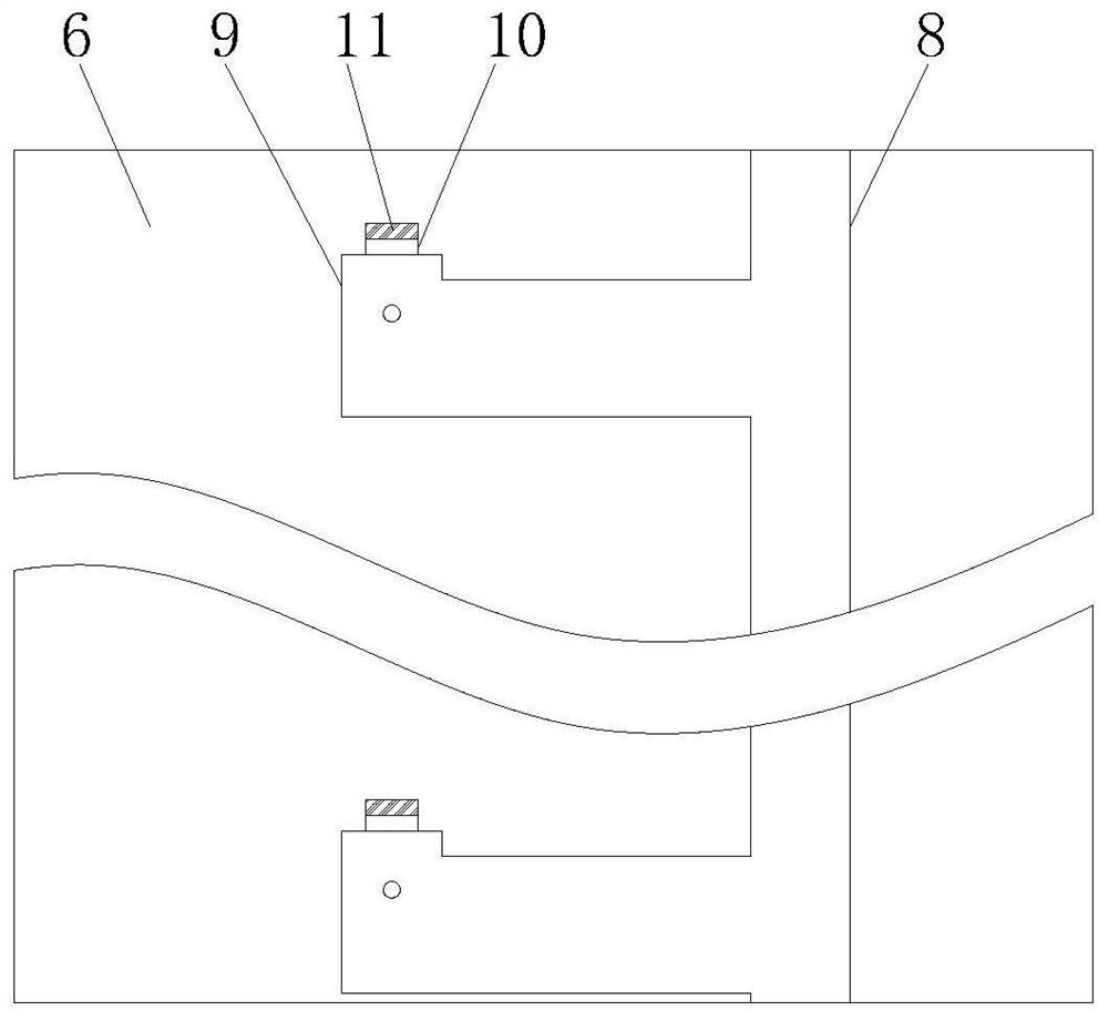
[0028] see Figure 1-7 As shown, a food sterilization equipment includes a sterilization box 1, a sterilization chamber 2 is arranged in the sterilization box 1, a workbench 3 is fixedly connected to the bottom end surface of the sterilization chamber 2, and the workbench 3. It is connected with the mounting base 5 through a rotating assembly, and both sides of the top of the mounting base 5 are fixedly connected with an arc-shaped support plate 6, and the arc-shaped support plate 6 is provided with a vertical slide groove 8, and the vertical slide One side of the groove 8 is evenly provided with a plurality of connection grooves, and the side of the connection groove away from the vertical chute 8 is provided with a fixed groove 9, and a placement plate 7 is arranged between the two arc-shaped support plates 6, so that Both end faces of the placement plate 7 are fixedly connected to the limit sleeve 12 through a support block, and the limit sleeve 12 is adapted to the vertica...

Embodiment 2

[0037] see Figure 8 As shown, Comparative Example 1 is another embodiment of the present invention; the top end surface of the workbench 3 is provided with an annular groove 30, and both sides of the bottom end surface of the mounting seat 5 are fixedly connected with support blocks 31, The support block 31 is slidingly connected with the annular groove 30, and balls are installed on the bottom of the support block 31, and the balls are fitted with the annular groove 30; The sliding fit between the grooves 30 facilitates the auxiliary support for the rotation of the mounting seat 5. The balls provided at the bottom of the support block 31 reduce the friction between the support block 31 and the annular groove 30, avoiding the friction between the support block 31 and the annular groove 30. 31 wear, prolonging the service life of the support.

[0038] Working principle, when the staff needs to place food of different volumes, slide the placement plate 7 along the vertical chu...


PUM


Abstract

The invention belongs to the technical field of food processing, and particularly relates to a food sterilization device. The food sterilization device comprises a sterilization box, wherein a sterilization cavity is formed in the sterilization box; the bottom end surface of the sterilization cavity is fixedly connected with a work table; the work table is connected with an installing seat through a rotating assembly; arc-shaped support plates are fixedly connected onto the two sides of the top of the installing seat; a vertical chute is formed in each arc-shaped support plate; and a plurality of connecting grooves are uniformly formed in one side of the vertical chute. Through the matching among a position limiting sleeve, a first spring and an I-shaped block, a placing plate can be preliminarily fixed in a fixing groove; workers can conveniently regulate the placing plate up and down along the vertical chute formed in the arc-shaped support plate so as to meet the requirement that food in different volumes can be put onto the placing plate to be sterilized; through the matching among a first magnetic block, a second magnetic block, a fixing block and a screw bolt, the position limiting sleeve can be further fixed in the fixing groove; and the placing plate is prevented from falling in the rotating process of the installing seat.

Description

technical field [0001] The invention relates to the technical field of food processing, in particular to food sterilization equipment. Background technique [0002] Food usually needs to be sterilized during processing, and most food sterilization technologies can be divided into: ultra-high pressure or ultra-high temperature sterilization technology, low temperature sterilization technology, pasteurization method, microwave sterilization technology, ultraviolet sterilization method and ozone sterilization technology. [0003] Since ultraviolet sterilization does not require heating, it will not damage the nutritional content of food, nor will it destroy the natural flavor of food, so ultraviolet sterilization technology has been widely used, but the existing ultraviolet food sterilization equipment does not have the ability to sterilize the chamber The function of height adjustment of the racks inside prevents the staff from making full use of the space of the racks for di...

Claims


Application Information

Patent Timeline
Patent Type & Authority Applications(China)
IPC IPC(8): A23L5/20A23L5/30
CPCA23L5/20A23L5/30
Inventor 谭锦玉
Owner 徐州凯佳食品有限公司
Why Eureka
Try Eureka