An automated eye examination robot
An ophthalmic examination and robotic technology, applied in medical science, equipment for testing eyes, and instruments for compressing reflex points, etc., can solve problems such as certain deviations in detection data, cumbersome examination steps, and eye fatigue of patients, etc. To achieve the effect of simplifying the detection steps, improving the accuracy and improving the accuracy
- Summary
- Abstract
- Description
- Claims
- Application Information
AI Technical Summary
Problems solved by technology
Method used
Image

Examples
Embodiment 1
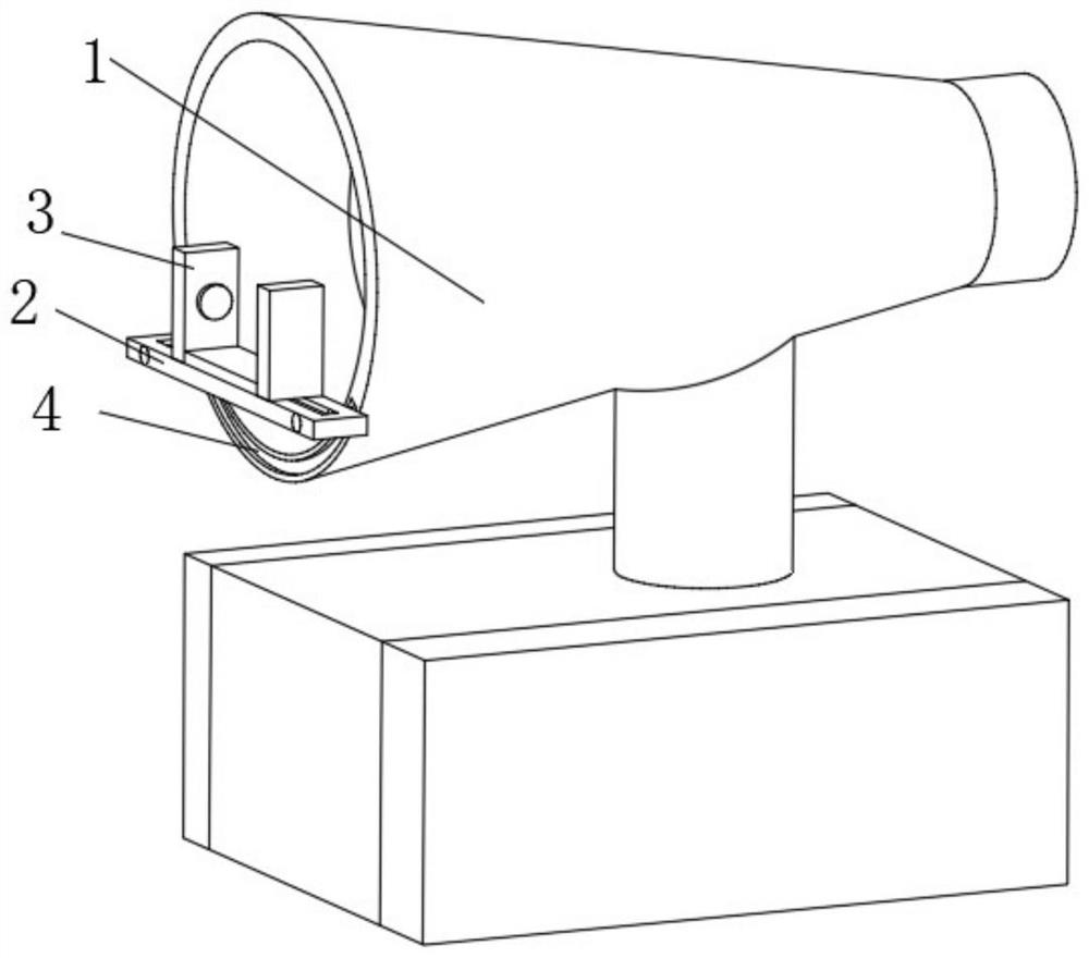
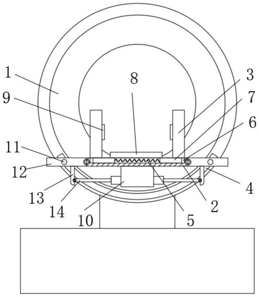
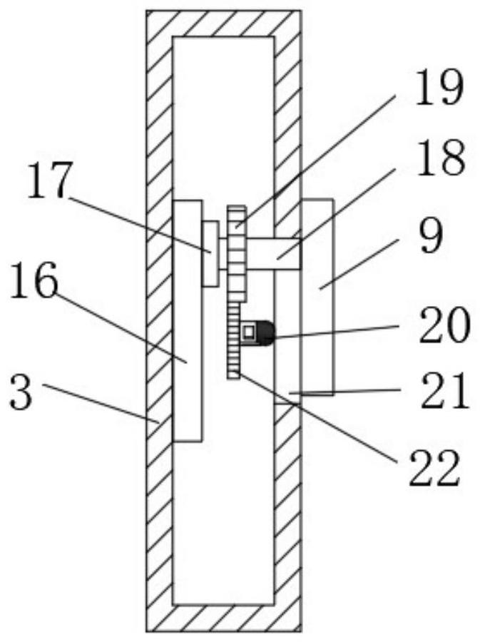
[0028] Example 1: Reference Figure 1-4 The shown automated ophthalmic inspection robot includes a cylindrical body 1, which is a common cylindrical ophthalmic inspection robot in the prior art, and the side wall of the cylindrical body 1 is The arc-shaped sliding groove 4 is slidably installed with two sliding rods 11, one end of the two sliding rods 11 is rotatably installed with a connecting plate 12, and a supporting plate 2 is rotatably installed between the two connecting plates 12, A groove 6 is provided on the side wall of the support plate 2, and two sliding plates 7 are slidably installed in the groove 6. One side of the two sliding plates 7 is fixedly installed with a mounting box 3, and one side of the mounting box 3 is provided with an annular opening. 21. A connecting rod 18 is slidably inserted in the annular opening 21. One end of the connecting rod 18 penetrates the annular opening 21 and is fixedly installed with the massage board 9. One side of the connectin...
Embodiment 2
[0035] Example 2: In Example 1, there is a problem that the device for relieving eye pressure is set up separately, which is inconvenient to work synchronously with the inspection robot, which makes the inspection steps cumbersome. Therefore, on the basis of Example 1, this implementation Examples also include:
[0036]As a preferred implementation of this embodiment, a fixing block 10 is fixedly installed on the lower side wall of the support plate 2, and a double-ended electric push rod 14 is fixedly inserted on the side wall of the fixing block 10. The double-ended electric push rod Both ends of the 14 are rotatably installed with a traction plate 13, and one end of the traction plate 13 is fixedly installed on one side of the connecting plate 12. This structural design can be used when the equipment stops working, through the movement of the double-ended electric push rod 14, thereby Make the traction plate 13 rotate with the connecting plate 12, and then make the connecti...
PUM
 Abstract
Description
Claims
Application Information
 - R&D
- Intellectual Property
- Life Sciences
- Materials
- Tech Scout
- Unparalleled Data Quality
- Higher Quality Content
- 60% Fewer Hallucinations
Browse by: Latest US Patents, China's latest patents, Technical Efficacy Thesaurus, Application Domain, Technology Topic, Popular Technical Reports.
© 2025 PatSnap. All rights reserved.Legal|Privacy policy|Modern Slavery Act Transparency Statement|Sitemap|About US| Contact US: help@patsnap.com