
Exhaust casing-oriented laser peening robot motion trail control method

A robot motion and trajectory control technology, applied in the field of surface treatment of parts, which can solve the problems of structural shading, low precision of surface spot overlap, and casing collision with light outlet.

Active Publication Date: 2021-09-14
AVIC BEIJING INST OF AERONAUTICAL MATERIALS
View PDF11 Cites 0 Cited by
  • Summary
  • Abstract
  • Description
  • Claims
  • Application Information

AI Technical Summary

Problems solved by technology

[0004] The object of the present invention is to propose a method for controlling the movement track of a laser shot peening robot facing the exhaust casing. Through this method, problems such as low lapping accuracy of curved light spots, structural shading, and casing collision with the light outlet can be solved, and the waiting time can be improved. The accessibility of the laser incident in the strengthening area improves the uniformity of the strengthening effect

Method used


Image

  • Exhaust casing-oriented laser peening robot motion trail control method
  • Exhaust casing-oriented laser peening robot motion trail control method
  • Exhaust casing-oriented laser peening robot motion trail control method

Examples


Embodiment

[0047] A method for controlling the motion trajectory of a laser peening robot facing an exhaust casing, comprising the following steps:

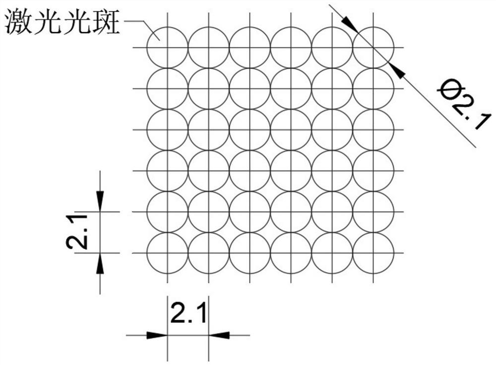
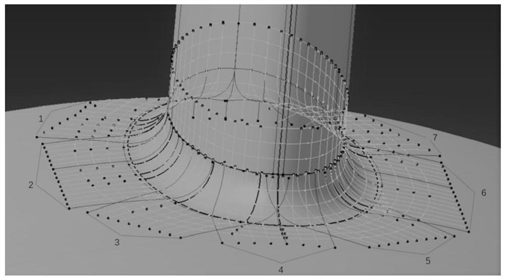
[0048] 1) Obtain the three-dimensional model of the exhaust casing and use UG software to read it; determine that the area to be strengthened is the transition fillet between the support plate of the exhaust casing and the outer flow channel; divide the surface of the area to be strengthened into a grid, and obtain the coordinates of the exhaust casing The coordinates of the grid points in the system; the diameter of the laser spot is Φ2.1mm, such as figure 1 As shown, the grid is divided by equidistant curves with a spacing of 2.1 mm, and multiple sets of equidistant curves are used to cover the area to be strengthened. The grid point after gridding is the center of the laser spot, as shown in figure 2 shown.

[0049] 2) Analyze the shielding of the strengthened area in other areas of the exhaust casing, determine the laser incident ang...


PUM


Abstract

The invention belongs to a part surface treatment technology, and relates to an exhaust casing-oriented laser peening robot motion trail control method. The position of an exhaust casing is determined through the X, Y and Z coordinates of the center of a flange plate of a robot, the posture of the exhaust casing installed on the flange plate of a wrist of the robot is controlled through the R, B and T axes, good operability and control precision are achieved, multi-angle incidence of laser can be achieved in space, and the possibility is provided for the optimization of the incidence angle; by adopting the method, the distribution uniformity of the residual compressive stress on the surface of a strengthened area is doubled, the position and incident angle of each laser spot can be accurately controlled, the adverse effects caused by curved surface and structure shielding and impact are reduced, the lap joint uniformity of a high-curvature part is improved, the laser accessibility of a structure shielding area is improved, the laser reachability of the structure shielding area is improved, and the surface quality of a to-be-strengthened area is improved.

Description

technical field [0001] The invention belongs to the component surface treatment technology, and relates to a method for controlling the motion trajectory of a laser shot peening robot facing an exhaust casing. Background technique [0002] The aero-engine exhaust casing is located at the tail of the engine and is mainly used to fix the engine turbine components and output the remaining gas. The exhaust case is usually made of high-temperature alloy casting, which bears multiple loads such as high-temperature heat flow impact and cyclic load. After service, high-temperature fatigue failure is prone to occur in the stress-concentrated parts such as the fillet of the support plate and the ejection groove. Laser shot peening is a new type of surface strengthening technology. By using the mechanical effect of laser, local plastic deformation occurs on the surface of the part to form a residual compressive stress field and a strengthening layer, thereby improving the high temperat...

Claims


Application Information

Patent Timeline
Patent Type & Authority Applications(China)
IPC IPC(8): B25J11/00B25J9/16B25J19/02
CPCB25J11/0065B25J9/1679B25J9/1669B25J19/022
Inventor 罗学昆王欣王强宋颖刚马世成许春玲宇波于洋
Owner AVIC BEIJING INST OF AERONAUTICAL MATERIALS
Learn More