
Three-mass four-parameter adjustable two-stage vibration reduction passive suspension and working method thereof

A technology of secondary vibration reduction and passive suspension, which is applied in suspension, elastic suspension, transportation and packaging, etc., can solve the problem that the overall performance of secondary vibration reduction passive suspension is not significantly improved, and the vibration acceleration of sprung mass is reduced. And other issues

Active Publication Date: 2021-09-14
尨腾汽车科技(南京)有限公司
View PDF4 Cites 2 Cited by
  • Summary
  • Abstract
  • Description
  • Claims
  • Application Information

AI Technical Summary

Problems solved by technology

[0003] The purpose of the present invention is to solve the problem that the overall performance of the existing secondary vibration-damping passive suspension is not obvious, and proposes a three-mass and four-parameter adjustable secondary vibration-damping passive suspension structure, and at the same time provides the suspension The working method, by setting the non-sprung mass (that is, the suspension first mass) and the sprung mass (that is, the second mass of the suspension), the third mass of the suspension, and the existing unsprung mass and sprung mass form a three-mass vibration structure, which can be greatly reduced under the same road surface roughness input. The vibration acceleration of the small spring-loaded mass; in addition, according to different vehicle load states, the stiffness and damping of the traditional vibration-damping structure, the stiffness and inertia of the anti-resonance vibration-damping structure are adjusted to improve the adaptability of the suspension to changes in vehicle loads

Method used


Image

  • Three-mass four-parameter adjustable two-stage vibration reduction passive suspension and working method thereof
  • Three-mass four-parameter adjustable two-stage vibration reduction passive suspension and working method thereof
  • Three-mass four-parameter adjustable two-stage vibration reduction passive suspension and working method thereof

Examples


Embodiment Construction

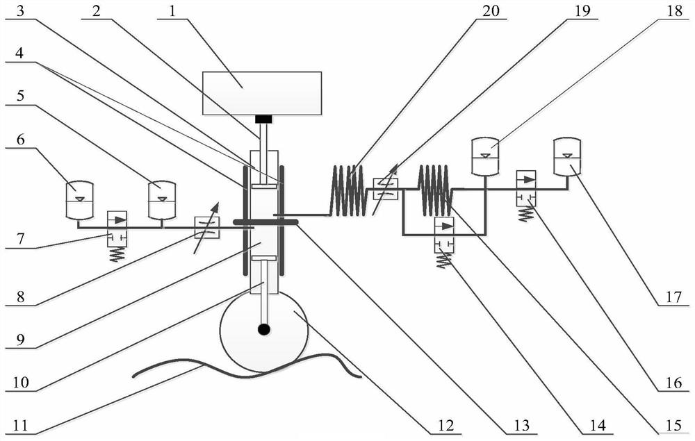
[0012] The three-mass four-parameter adjustable secondary vibration-damping passive suspension described in the present invention is installed between the wheel 12 and the vehicle body 1 above it, and is composed of a traditional vibration-damping structure with adjustable stiffness and damping, the third mass 4 of the suspension, It consists of an anti-resonance damping structure with adjustable stiffness and inertia.

[0013] The traditional damping structure is composed of a first oil cylinder 9 , a first piston rod 10 , a first adjustable throttle valve 8 , a second accumulator 5 , a first electromagnetic valve 7 and a first accumulator 6 . Wherein, the first oil cylinder 9 is arranged vertically up and down, with the bottom facing upward. The upper end of the first piston rod 10 is the piston end, extending in the first oil cylinder 9 to divide the first oil cylinder 9 into upper and lower chambers, the lower chamber has a vent hole to communicate with the outside, the up...


PUM


Abstract

The invention discloses a three-mass four-parameter adjustable two-stage vibration reduction passive suspension and a working method thereof. The suspension comprises a traditional vibration reduction structure composed of a first oil cylinder, a first piston rod, a first adjustable throttling valve, a second energy accumulator, a first electromagnetic valve and a first energy accumulator, the suspension also comprises an anti-resonance vibration reduction structure composed of a second oil cylinder, a second piston rod, a first inerter spiral pipe, a second adjustable throttling valve, a second inerter spiral pipe, a second electromagnetic valve, a third energy accumulator, a third electromagnetic valve and a fourth energy accumulator, and the cylinder body of the first oil cylinder and the cylinder body of the second oil cylinder are fixedly connected with a suspension third mass. The suspension third mass vibrates to absorb a part of sprung mass vibration energy input, the sprung mass vibration acceleration is greatly reduced, the working states of the adjustable throttling valves and all the electromagnetic valves can be conveniently adjusted according to the load state of an automobile, and a good suspension comprehensive performance index improvement effect can be achieved under different automobile load states.

Description

technical field [0001] The invention belongs to the field of automobile suspensions, in particular to a two-stage damping suspension structure and a working method thereof, which can effectively damp the automobiles. Background technique [0002] Suspension is an important structural component of a car, which has an important impact on the ride comfort and handling stability of the car. Classified according to the ability of the actuator, the suspension can be divided into three categories: passive suspension, active suspension and semi-active suspension. In addition to actuators, active suspensions and semi-active suspensions must also include sensors and controllers to form a feedback control system, so the system complexity and manufacturing cost are relatively high. At present, passive suspensions mainly use different designs of elastic elements, damping elements, and inertial elements to obtain better comprehensive suspension performance than traditional suspensions wi...

Claims


Application Information

Patent Timeline
Patent Type & Authority Applications(China)
IPC IPC(8): B60G13/08B60G17/08
CPCB60G13/08B60G17/08
Inventor 陈勰文
Owner 尨腾汽车科技(南京)有限公司
Learn More