Tunneling trolley
A technology for excavating trolleys and benches, which can be used in shaft linings, tunnel linings, underground chambers, etc., and can solve problems such as the stability of falling jackhammer placement
- Summary
- Abstract
- Description
- Claims
- Application Information
AI Technical Summary
Problems solved by technology
Method used
Image

Examples
Embodiment 1
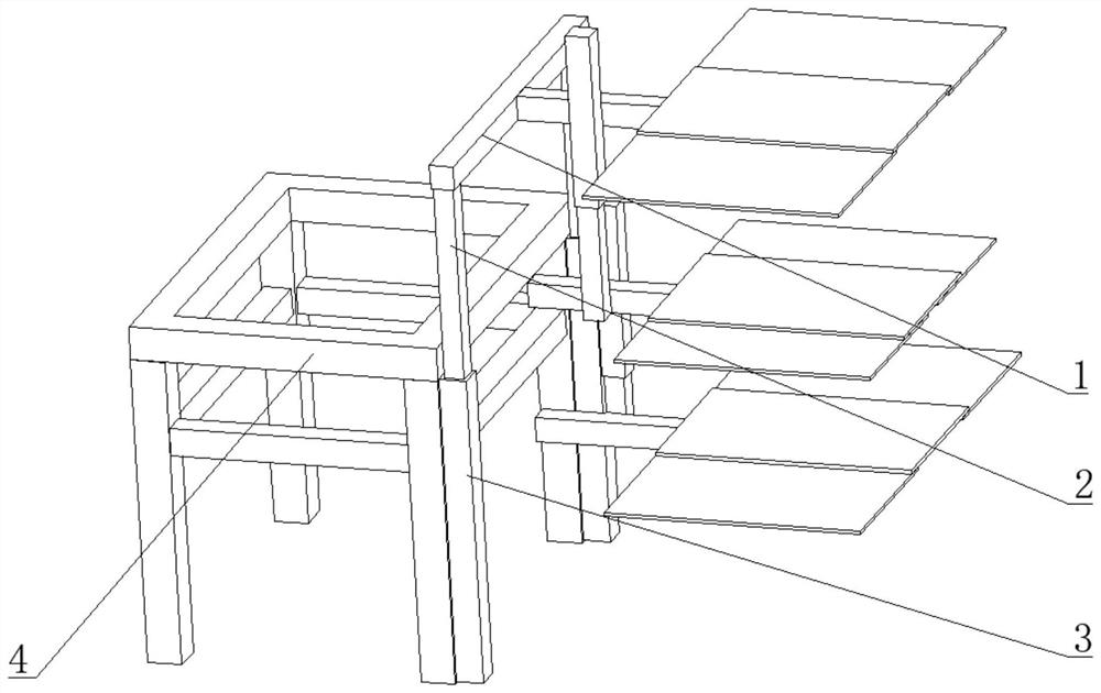
[0047] Embodiment 1: Operate the device to a designated location. When it is necessary to adjust the overall height of the three-layer platform (the platform on each floor includes the middle platform 10 and the two side platforms 11), open the electric push rod 2 9, and the electric push rod 2 9 drives the hollow square rod 1 2 along the The hollow square rod two 3 moves, the hollow square rod one 2 drives the support rod 1 to move, and the support rod 1 drives the platform mechanism to move, so as to realize the overall height adjustment of the three-layer platform.
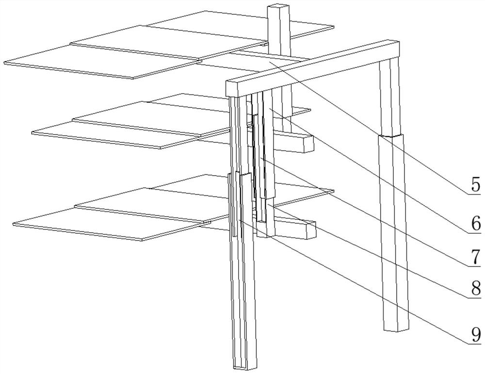
[0048] When adjusting the distance between adjacent stands, take adjusting the distance between two stands on the upper side as an example, open the corresponding electric push rod one 7, and the electric push rod one 7 drives the upper hollow square rod four 8 along the upper hollow square rod three 6 Move, the upper hollow square rod four 8 drives the middle square rod 5, the middle stand one 10, the two side...
Embodiment 2
[0050] Embodiment 2: Operate the device to a designated location. When needing to adjust the height of the stand mechanism, open the electric push rod 2 9 to realize the height adjustment of the stand mechanism.
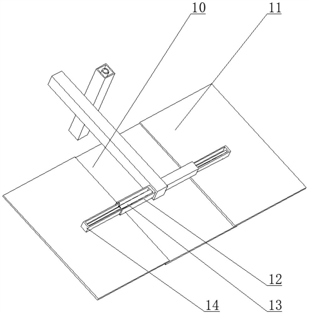
[0051] When adjusting the two 26 and 15 distances between the two pedestals on both sides. Take the platform two 26 on both sides of the upper side and the middle platform two 15 as examples, unscrew the two jacking screws 18 on the upper side, turn on the motor 21, the motor 21 drives the screw rod 22 to rotate, and the screw rod 22 drives the lower hollow round rod 20 to move, and the lower side hollow rod 20 moves. The side hollow round rod 20 drives the trapezoidal chute 19 to move, the trapezoidal chute 19 drives the upper side hollow round rod 20 to move along the upper side round bar 24, the trapezoidal chute 19 drives the trapezoidal slider 28 to move, and the trapezoidal slider 28 drives the round bar The second 27 moves along the chute 17, the round bar tw...
PUM
 Abstract
Description
Claims
Application Information
 - R&D
- Intellectual Property
- Life Sciences
- Materials
- Tech Scout
- Unparalleled Data Quality
- Higher Quality Content
- 60% Fewer Hallucinations
Browse by: Latest US Patents, China's latest patents, Technical Efficacy Thesaurus, Application Domain, Technology Topic, Popular Technical Reports.
© 2025 PatSnap. All rights reserved.Legal|Privacy policy|Modern Slavery Act Transparency Statement|Sitemap|About US| Contact US: help@patsnap.com