Method for solving nonlinear power system tie line feasible region

A power system and tie line technology, applied in the field of solving the feasible region of nonlinear power system tie lines, can solve problems such as ignoring reactive power and voltage, ignoring regional power flow balance constraints, restrictions, etc.

Active Publication Date: 2021-09-14
GUANGXI UNIV
View PDF13 Cites 0 Cited by
  • Summary
  • Abstract
  • Description
  • Claims
  • Application Information

AI Technical Summary

Problems solved by technology

For example, the network flow method ignores the power flow balance constraints of the regional power grid; although the bread...

Method used


Image

  • Method for solving nonlinear power system tie line feasible region
  • Method for solving nonlinear power system tie line feasible region
  • Method for solving nonlinear power system tie line feasible region

Examples


Embodiment 1

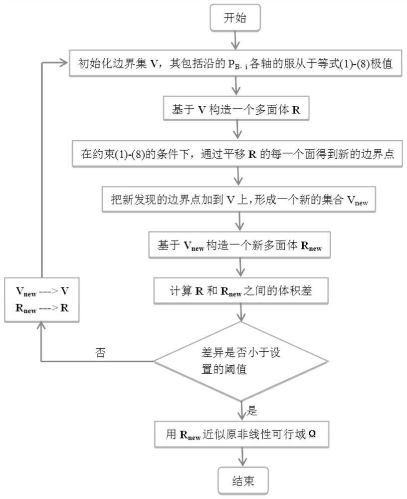
[0048] see figure 1 , a method for solving the feasible region of a nonlinear power system tie line, comprising the following steps:

[0049] 1) Establish constraints for tie line feasible region calculation.

[0050] The constraints include power balance constraints, transmission constraints, generator power constraints, and tie line power thermal constraints.

[0051] The power balance constraints include regional power flow constraints of active power balance and reactive power balance, namely:

[0052]

[0053]

[0054] In the formula, is the collection of buses in the grid. P L,i , P B,i and PG,i are the active load power, active tie line power and active generation level at bus i, respectively. Q L,i , Q B,i and Q G,i are the reactive load power, reactive tie line power and reactive power generation level at bus i, respectively. V i and V j are the voltage values ​​at bus bar i and bus bar j, respectively. G ij and B ij are the conductance and admit...

Embodiment 2

[0084] A method for solving the feasible region of a tie line of a nonlinear power system, comprising the following steps:

[0085] 1) Establish constraints

[0086] a) Power balance constraints

[0087] The regional power system power flow constraints including active and reactive power balance can be represented by the following matrices and vectors:

[0088]

[0089]

[0090] in the formula is the set of buses in the grid; P L,i , P B,i , and P G,i are the active load power at bus i, active tie line power and active generation level; Q L,i , Q B,i , and Q G,i are the reactive load power at bus i, the reactive tie line power and the reactive power generation level; V i and V j are the voltage values ​​at busbars i and j, respectively; G ij and B ij are the conductance and admittance of the i-j branch of the busbar, respectively; θ ij is the difference between the voltage phase angles at bus i and j.

[0091] b) Transmission constraints

[0092] The trans...

Embodiment 3

[0118] An accuracy verification test of a method for solving the feasible region of a tie line of a nonlinear power system, including the following procedures:

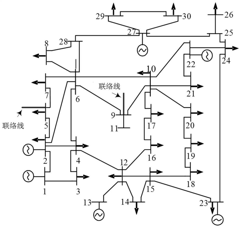
[0119] 1) Establish an IEEE-30 bus system, see figure 2 .

[0120] 2) Use the following three methods to describe the feasible area:

[0121] M0: Monte Carlo sampling method.

[0122] M1: Multi-segment boundary approximation method.

[0123] M2: The maximum transmission power method of the tie line.

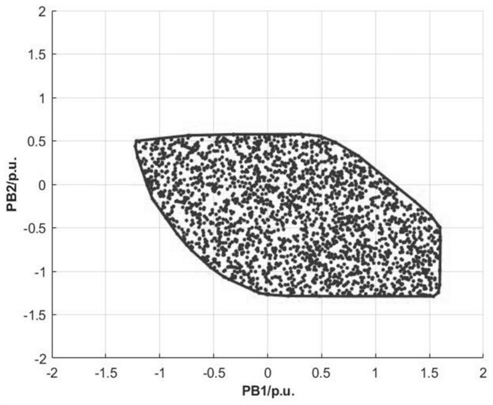
[0124] like Figure 3-5 As shown, the feasible regions of the IEEE-30 node system are respectively described by the above three methods. PB1 and PB2 are the transmission power of the boundary tie line. Among them, positive values ​​represent the tie-line power injected from other adjacent area networks to the boundary nodes of the area network, and negative values ​​represent the tie-line power transmitted to other adjacent area networks.

[0125] like image 3 As shown, 5000 points are randomly sampled, and the...


PUM


Abstract

The invention discloses a method for solving a nonlinear power system tie line feasible region. The method comprises the following steps of: 1) establishing a constraint condition for calculating a tie line feasible region; 2) establishing a boundary set V; 3) establishing a polyhedron R based on the boundary set; 4) translating at least one surface of the polyhedron R to obtain a plurality of new boundary points meeting constraint conditions, and writing new boundaries into the boundary set V to obtain a new boundary set Vnew; 5) establishing a new polyhedron Rnew based on the new boundary set Vnew; and 6) judging whether the difference between the polyhedron R and the new polyhedron Rnew is smaller than a preset condition, if so, obtaining a power system tie line feasible region Rnew, otherwise, updating the boundary set V to be Vnew, updating the polyhedron R to be Rnew, and returning to the step 4). According to the method, the original tie line feasible region can be effectively approximated, the original nonlinear feasible region is approximated to the linear feasible region, the calculation amount is small, and the precision is high.

Description

technical field [0001] The invention relates to the field of nonlinear power system calculation, in particular to a method for solving the feasible region of a tie line of a nonlinear power system. Background technique [0002] With the ever-increasing demand for electricity and renewable energy sources, the efficient use of power resources in regional power grids is increasingly dependent on the exchange of power from tie lines in interconnected power grids. The feasible region is a space where the system can run stably under the operational constraints and safety constraints. The accurate description of the feasible region of the tie line ensures the optimality and safety of power dispatching. However, the tie-line feasible region is usually complicated due to the existence of nonlinear constraints. Improper determination of tie line power will violate grid operation constraints, including unit output constraints and voltage amplitude constraints. Therefore, it is very n...

Claims


Application Information

Patent Timeline
IPC IPC(8): H02J3/00G06F17/15
CPCH02J3/00G06F17/15H02J2203/20
Inventor 代伟简江艺王帅赵静怡石博臣
Owner GUANGXI UNIV
Why Eureka
Try Eureka