Heat dissipation device

A heat dissipation device and heat source technology, applied in heat exchange equipment, lighting and heating equipment, modification through conduction heat transfer, etc., can solve problems such as electromagnetic wave interference, copper or stainless copper oxidation, and reduced reliability

Pending Publication Date: 2021-09-14
ZYXEL NETWORKS CORP
View PDF6 Cites 0 Cited by
  • Summary
  • Abstract
  • Description
  • Claims
  • Application Information

AI Technical Summary

Problems solved by technology

However, the cost of copper or stainless steel is relatively high, and under long-term high temperature conditions, copper or stainless copper will be oxidized, thereby reducing reliability
If lower-cost aluminum is used as the material of the metal shell, pure water will corrode aluminum, so the coolant can only use acetone, which has a high degree of environmental pollution
In addition to the problem of high cost, the metal shell is also easy to form an antenna to radiate high-speed signals, thereby causing the problem of electromagnetic wave interference

Method used


Image

  • Heat dissipation device
  • Heat dissipation device
  • Heat dissipation device

Examples


Embodiment Construction

[0054] Reference will now be made in detail to the exemplary embodiments of the present invention, examples of which are illustrated in the accompanying drawings. Wherever possible, the same reference numbers will be used in the drawings and description to refer to the same or like parts.

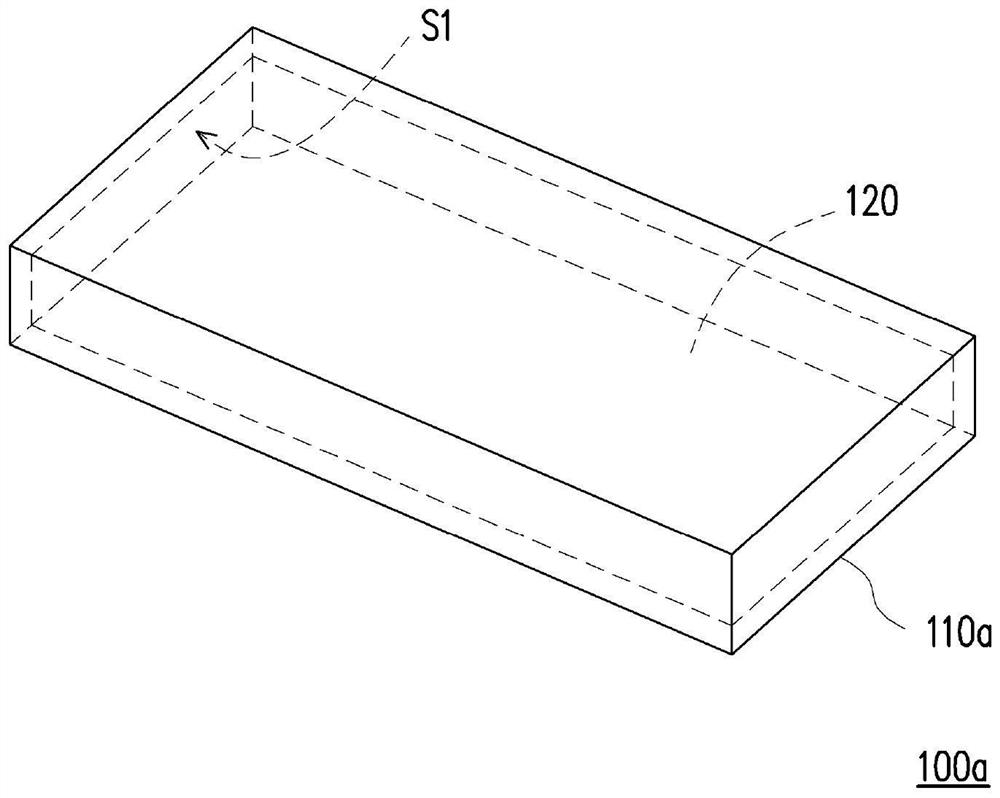
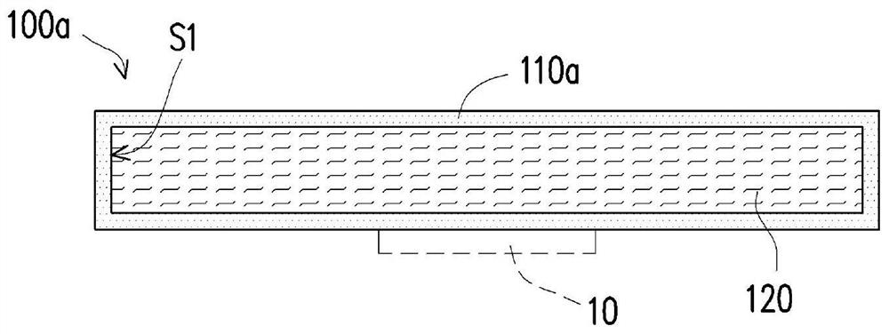
[0055] Figure 1A is a three-dimensional schematic diagram of a heat dissipation device according to an embodiment of the present invention. Figure 1B yes Figure 1A A cross-sectional schematic diagram of the heat sink. Please also refer to Figure 1A and Figure 1B, in this embodiment, the heat dissipation device 100a is suitable for dissipating heat from at least one heat source 10 in the electronic system. Here, the electronic system is, for example, a network communication system, where the main electrical specifications of the network communication system include an interface with high-speed transmission, a multi-port (Port) network switch (Ethernet switch), optical fiber communicat...


PUM


Abstract

A heat dissipation device is provided and is suitable for heat dissipation of a heat source in an electronic system. The heat dissipation device includes a thermally conductive plastic shell and a fluid. The thermally conductive plastic shell has at least one sealed accommodation space. The fluid completely fills the at least one sealed accommodation space of the thermally conductive plastic shell. The heat dissipation device is suitable for heat dissipation of a heating source in an electronic system, has the advantages of being low in cost and easy to produce, and does not additionally generate the problem of electromagnetic wave interference.

Description

technical field [0001] The invention relates to a heat dissipation device, and in particular to a heat dissipation device applied in an electronic system. Background technique [0002] With the advent of the 5G era, network communication equipment products are developing towards the trend of short, small, light and thin. With the high performance and high transmission rate of electronic products, the heating power of electronic components and systems is also increasing, and the heat flux density of electronic components is also increasing. In network communication equipment, effectively solving the heat dissipation problem has become a key technology. [0003] At present, the cooling devices applied to network communication equipment mainly adopt liquid-cooled metal radiators, and the materials used are copper, stainless steel or aluminum. If copper or stainless steel is used as the material of the metal shell, pure water can be used as the cooling liquid. However, the co...

Claims


Application Information

Patent Timeline
Patent Type & Authority Applications(China)
IPC IPC(8): H05K7/20
CPCH05K7/20254H05K7/2039H05K7/20509F28F21/06H01L23/42H05K7/20218F28F21/062
Inventor 江律纬陈亮维简辉龙
Owner ZYXEL NETWORKS CORP
Why Eureka
Try Eureka