Guiding type artificial oropharynx channel sputum suction device and working method

A guided and manual technology, applied in the direction of suction devices, drug devices, and other medical devices, can solve the problems of large left and right swings of the sputum suction tube, difficulty in aligning the larynx to suck sputum, and deviation from the top of the larynx, etc., to achieve Ease of suction operation, high signal-to-noise ratio, and long service life

Active Publication Date: 2021-09-17
SHANDONG UNIV
View PDF14 Cites 0 Cited by
  • Summary
  • Abstract
  • Description
  • Claims
  • Application Information

AI Technical Summary

Problems solved by technology

[0004] During the process of collecting sputum, due to the relatively large inner diameter of the artificial oropharyngeal channel, the sputum suction tube swings too much left and right, making it difficult to align the upper part of the larynx and suck sputum; the shape of the oropharyngeal channel is curved, resulting in When the sputum tube is advanced, it is often blocked in the oropharynx; or even if it is advanced to the patient's throat near the epiglottis, it often deviates from the top of the larynx, causing the suction tube passing through the oropharyngeal passage to also deviate from the top of the larynx and cannot enter the trachea; During sputum collection, the patient was still breathing, and the end-tidal carbon dioxide (ETCO 2 ) concentration will be interfered by impurity gases, which will affect the test results

Method used


Image

  • Guiding type artificial oropharynx channel sputum suction device and working method
  • Guiding type artificial oropharynx channel sputum suction device and working method
  • Guiding type artificial oropharynx channel sputum suction device and working method

Examples


Embodiment 1

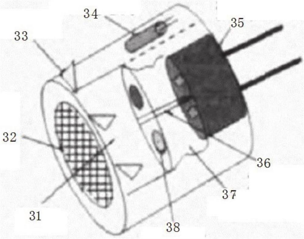
[0041] Such as figure 1 As shown in -7, a guided artificial oropharyngeal channel sputum suction device includes: a straight tube and a curved tube, the straight tube and the curved tube are connected, the inner sleeve is sleeved on the inner side of the pipeline formed by the straight tube and the curved tube, and the inner sleeve The tube includes at least one set of guide tubes and at least one set of sputum suction tubes. The guide tubes and the sputum suction tubes are arranged side by side. An infrared light sensor is arranged inside the guide tube. The nozzle on the side is flush with the nozzle of the sputum suction tube, and the infrared light sensor is connected with the detection host.

[0042] The infrared light sensor is located at the mouth of the guide tube.

[0043] There are scales on the surface of the suction tube.

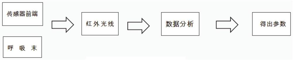
[0044] The infrared light sensor acquires the carbon dioxide concentration and gas flow rate of the gas flowing through the guide tube and tr...

Embodiment 2

[0077] The present embodiment provides the working method of the above-mentioned device, comprising the following steps:

[0078] Using an infrared light sensor to obtain the carbon dioxide concentration and gas flow rate of the gas flowing through the guide tube;


PUM


Abstract

The invention relates to a guiding type artificial oropharynx channel sputum suction device and a working method. The guiding type artificial oropharynx channel sputum suction device comprises a straight pipe and a bent pipe, the straight pipe is connected with the bent pipe, a pipeline formed by the straight pipe and the bent pipe sleeves an inner sleeve, the inner sleeve comprises at least one group of guiding pipes and at least one group of sputum suction pipes, and the guiding pipes and the sputum suction pipes are arranged in parallel; and infrared light sensors are arranged in the guiding pipes, pipe openings of the guiding pipes are located at a pipe opening of the bent pipe, the pipe openings, close to one side of the infrared light sensor, of the guiding pipes are flush with pipe openings of the sputum suction pipes, and the infrared light sensor is connected with a detection host. The position of the throat is determined according to the end-breath carbon dioxide concentration and the gas flow rate obtained by the infrared light sensor, so that sputum suction operation is facilitated.

Description

technical field [0001] The invention relates to the field of medical equipment, in particular to a guided artificial oropharyngeal channel sputum suction device and a working method. Background technique [0002] The statements in this section merely provide background information related to the present invention and do not necessarily constitute prior art. [0003] The artificial oropharyngeal passage device is commonly used clinically to help patients maintain a smooth airway, and can also be used to collect and analyze the patient's sputum to find pathogenic bacteria. For such patients, the sputum collection operation needs to pass the sputum suction tube through the artificial oropharyngeal channel device to reach the top of the throat to suck the sputum, so as to avoid mixing with saliva and prevent the bacteria in the saliva from interfering with the purity of the sputum, resulting in inaccurate detection. precise. [0004] During the process of collecting sputum, du...

Claims


Application Information

Patent Timeline
IPC IPC(8): A61M1/00
CPCA61M2230/432A61M2230/40A61M2230/005
Inventor 周生余秦念博孙海航张发艳李玮
Owner SHANDONG UNIV
Why Eureka
Try Eureka