
Roller and rolling mill and application thereof

A technology of rolls and rolling mills, which is applied to rolls and their rolling mills and application fields. It can solve problems such as damage to product quality, scratches on the surface of work rolls, bump marks, etc., so as to prolong the service life, eliminate scratches, and improve product quality. Effect

Active Publication Date: 2021-09-17
SHANXI TAIGANG STAINLESS STEEL CO LTD
View PDF20 Cites 0 Cited by
  • Summary
  • Abstract
  • Description
  • Claims
  • Application Information

AI Technical Summary

Problems solved by technology

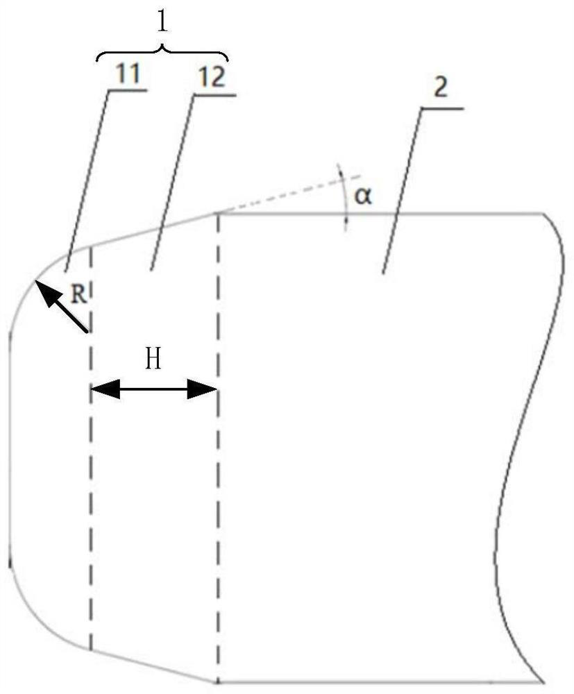
The roll end of the existing roll is at a 90° right angle. During the transportation, storage, installation or handling of the roll, the right angle roll end will inevitably scratch the surface of other rolls and affect the surface quality of the rolled product.
[0003] Multi-roll mills (especially 20-roll mills, the archway structure is closed and the space is narrow), the work rolls need to be replaced frequently during the production process, and the narrow space will cause the work rolls to collide frequently when the work rolls are plugged. The edges and corners of the middle roll end will cause the surface of the work roll to be rubbed, scratched, bumped, and printed on the surface of the steel plate during rolling, which will seriously damage the product quality
[0004] In order to avoid the above-mentioned defects, the research and development personnel developed a roll with straight chamfers at the end of the roll. However, during the process of plugging or handling, the straight edges and right angles of the roll end still cannot avoid bumping the roll body of other rolls.
In addition, the research and development personnel have also developed a roll with rounded corners at the end of the roll. However, when the roll is a new roll, the rounded corners are complete and can protect other rolls, but as the diameter of the grinding roll changes Thin, sharp corners will still be formed at the end of the roll, and the corners will still hit the roll surface of other rolls (such as work rolls) during the plugging process

Method used


Image

  • Roller and rolling mill and application thereof

Examples


Embodiment

[0046] The present invention is further illustrated below by means of examples, but the present invention is not limited to the scope of the examples. For the experimental methods not indicating specific conditions in the following examples, follow conventional methods and conditions.

[0047] The 12# rolling mill of Shanxi Taiyuan Iron and Steel Co., Ltd. is a 20-high rolling mill, and the size specification of the first intermediate roll is the diameter of the roll body The fillet radius of the first roll end is 10 mm, the height of the second roll end is 10 mm, and the included angle between the second roll end and the roll body is 14°. When producing high-grade products such as BA boards, compared with the traditional first intermediate roll, the first intermediate roll of the present invention has better rolls for rolling mills, cold lines, and quality inspection feedback. The specific performances are as follows: ① The surface quality of the product is significantly imp...


PUM


Abstract

The invention belongs to the technical field of stainless steel cold rolling, and particularly relates to a roller and a rolling mill and application thereof. The roller comprises a roller body and at least one roller end connected to one end of the roller body, wherein the roller end comprises a first roller end and a second roller end connected with the first roller end; the second roller end is connected with the roller body; the first roller end is rounded, the second roller end is in a frustum shape, and the outer surface of the second roller end is tangent to the rounded corner of the first roller end. According to the roller disclosed by the invention, the roller end structure with the rounded corner and the inclined surface is adopted, so that the roller end can be prevented from scratching the roller surfaces of other rollers in the processes of carrying, mounting and the like of the roller.

Description

technical field [0001] The invention belongs to the technical field of stainless steel cold rolling, and in particular relates to a roll, rolling mill and application thereof. Background technique [0002] The roll is the main working part and tool for continuous plastic deformation of the metal on the rolling mill. It is mainly composed of three parts: the roll body, the roll neck and the shaft head. Among them, the roll body is the middle part of the roll that actually participates in rolling metal. Therefore, the smoothness of the roll body surface directly affects the quality of the steel strip. The roll end of the existing roll is at a 90° right angle. During the transportation, storage, installation or handling of the roll, the right angle roll end will inevitably scratch the surface of other rolls and affect the surface quality of the rolled product. [0003] Multi-roll mills (especially 20-roll mills, the archway structure is closed and the space is narrow), the wor...

Claims


Application Information

Patent Timeline
Patent Type & Authority Applications(China)
IPC IPC(8): B21B27/02
CPCB21B27/02
Inventor 段维芳雷功梁敏诤贾江宏曹国志郭红运王建荣
Owner SHANXI TAIGANG STAINLESS STEEL CO LTD
Learn More