
Rolling mill rolling pressure measuring method

A technology of rolling pressure and measurement method, applied in the direction of metal rolling, metal rolling, length measuring device, etc., can solve the problems of insufficient precision, different, affecting the thickness control precision of rolled sheets, etc. Effect

Active Publication Date: 2021-09-17
武汉钢铁有限公司
View PDF10 Cites 0 Cited by
  • Summary
  • Abstract
  • Description
  • Claims
  • Application Information

AI Technical Summary

Problems solved by technology

However, the oil pressure of the hydraulic cylinder of the rolling mill is not equal to the rolling force of the rolling mill. The main reasons are the internal leakage of the hydraulic oil, the variable stiffness characteristics of the hydraulic cylinder, and the gap and friction between the vertical interfaces of the rolling mill roll system. The accuracy of the rolling force measurement Directly affects the control accuracy of the rolled plate thickness
Therefore, during use, the oil pressure of the hydraulic cylinder is generally different from the actual rolling pressure, and the deviation value does not have a quantitative index
[0003] In addition, the pressure difference in the same direction is usually used to determine whether the pressure measurement is accurate, that is, a pressure sensor (pressure measuring head) is installed at the lower part of the work roll under the rolling mill. During the production process, the pressure obtained at the two places is measured at the same time. If the value is large, it is judged that the actual measurement accuracy is not good, and the equipment needs to be repaired
However, there is a problem of insufficient precision in this judgment method.

Method used


Image

  • Rolling mill rolling pressure measuring method

Examples


Embodiment Construction

[0015] The present invention will be further described in detail below in conjunction with the accompanying drawings and specific embodiments.

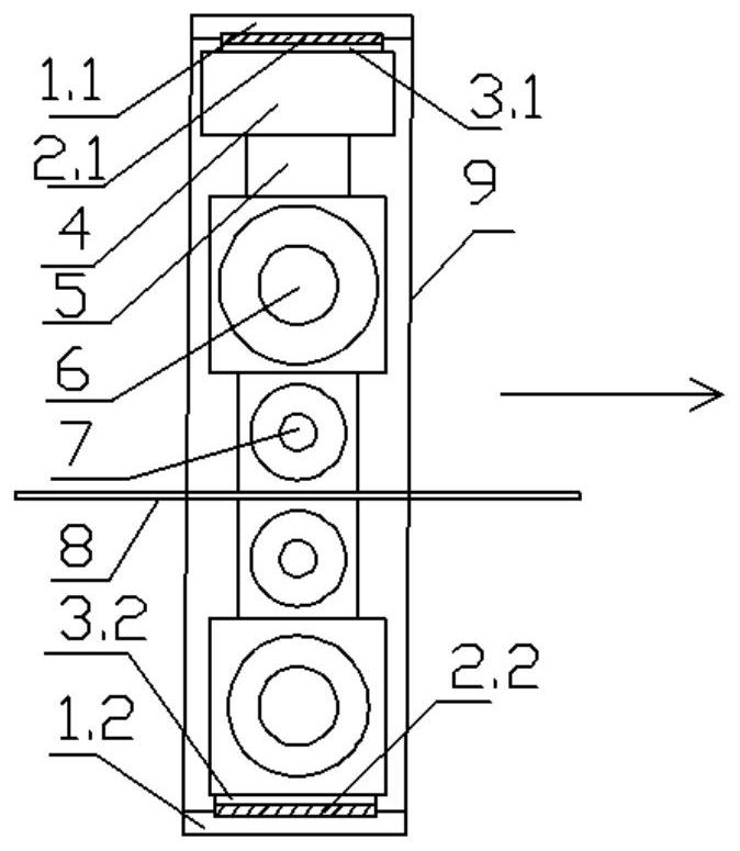
[0016] Such as figure 1 The device shown is a rolling force measuring device for a rolling mill. Below the lower support roller, there are installed the lower pressure measuring upper equalizing plate 3.2, the lower pressure sensor 2.2, and the lower equalizing plate 1.2; on the upper part of the upper supporting roller 6, the hydraulic pressure head 5, the hydraulic cylinder 4, the upper pressure measuring and the lower equalizing plate 3.1 are successively installed , the upper pressure sensor 2.1, the upper pressure measuring and upper equalizing plate 1.1. The function of the pressure equalizing plate is to make the pressure distribution uniform so as to obtain a more realistic pressure measurement value. Between the upper support roll 6 and the lower support roll, an upper work roll 7 and a lower work roll are arranged respecti...


PUM


Abstract

The invention discloses a rolling mill rolling pressure measuring method. The method comprises the following steps that a rolling mill rolling force measuring device is arranged, the device comprises a lower pressure measuring upper pressure equalizing plate, a lower pressure sensor and a lower pressure measuring lower pressure equalizing plate which are sequentially arranged below a lower support roller, and the device further comprises a pressure measuring pressure head, a hydraulic cylinder, an upper pressure measuring lower pressure equalizing plate, an upper pressure sensor and an upper pressure measuring upper pressure equalizing plate which are sequentially arranged above an upper support roller; and pressure measured by the upper pressure sensor is working side pressure Fw1, transmission side pressure Fd1, working side hydraulic cylinder pressure Mw, transmission side hydraulic cylinder pressure Md, and pressure measured by the pressure sensor at the position of the lower support roller is working side pressure Fw2 and transmission side pressure Fd2. By means of the method, the rolling mill rolling force can be corrected, the real rolling force is obtained and serves as a basis for plate thickness adjustment, the beneficial effect is achieved for effectively improving the functional precision of a rolling mill, and application and popularization value is achieved.

Description

technical field [0001] The invention relates to a pressure measuring method, in particular to a rolling mill rolling pressure measuring method, and belongs to the technical field of hot rolling mill pressure measurement. Background technique [0002] For rolling mills, especially hot rolling mills, the rolling pressure is the key factor to control the thickness of the rolling mill. In the actual production process, the rolling pressure is provided by the hydraulic cylinder on the top of the rolling mill. Pressure measurement generally adopts the method that the oil pressure of the hydraulic cylinder is equal to the pressing pressure of the rolling mill. However, the oil pressure of the hydraulic cylinder of the rolling mill is not equal to the rolling force of the rolling mill. The main reasons are the internal leakage of the hydraulic oil, the variable stiffness characteristics of the hydraulic cylinder, and the gap and friction between the vertical interfaces of the rollin...

Claims


Application Information

Patent Timeline
IPC IPC(8): B21B38/06B21B38/08
CPCB21B38/06B21B38/08
Inventor 邱碧涛周坤袁金朱凯龚旭李家波陈燕才邓杨何可
Owner 武汉钢铁有限公司
Learn More