Vehicle lifting equipment for new energy battery replacement

A battery replacement and new energy technology, applied in vehicle maintenance, electric vehicles, vehicle energy storage, etc., can solve the problems of battery installation method errors, batteries not being installed correctly in the car, etc.

Active Publication Date: 2021-09-17
STATE GRID XINJIANG ELECTRIC POWER COMPANY HAMI POWER SUPPLY
View PDF6 Cites 6 Cited by
  • Summary
  • Abstract
  • Description
  • Claims
  • Application Information

AI Technical Summary

Problems solved by technology

[0003] In the existing new energy vehicle battery replacement technology, the driver needs to drive the new energy vehicle into the new energy replacement station, lift the vehicle through a jack, remove the old battery through other equipment, and replace the fully charged new battery. Quickly move into the bottom of the car for installation. Due to the inconsistent driving and parking positions of the car, there are errors in this method of installing the battery, which may cause the battery to not be installed correctly in the car

Method used


Image

  • Vehicle lifting equipment for new energy battery replacement
  • Vehicle lifting equipment for new energy battery replacement
  • Vehicle lifting equipment for new energy battery replacement

Examples


Embodiment 1

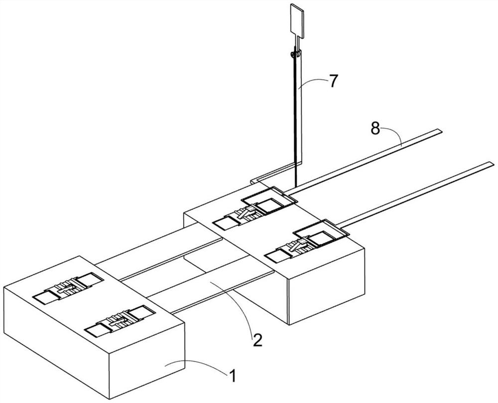
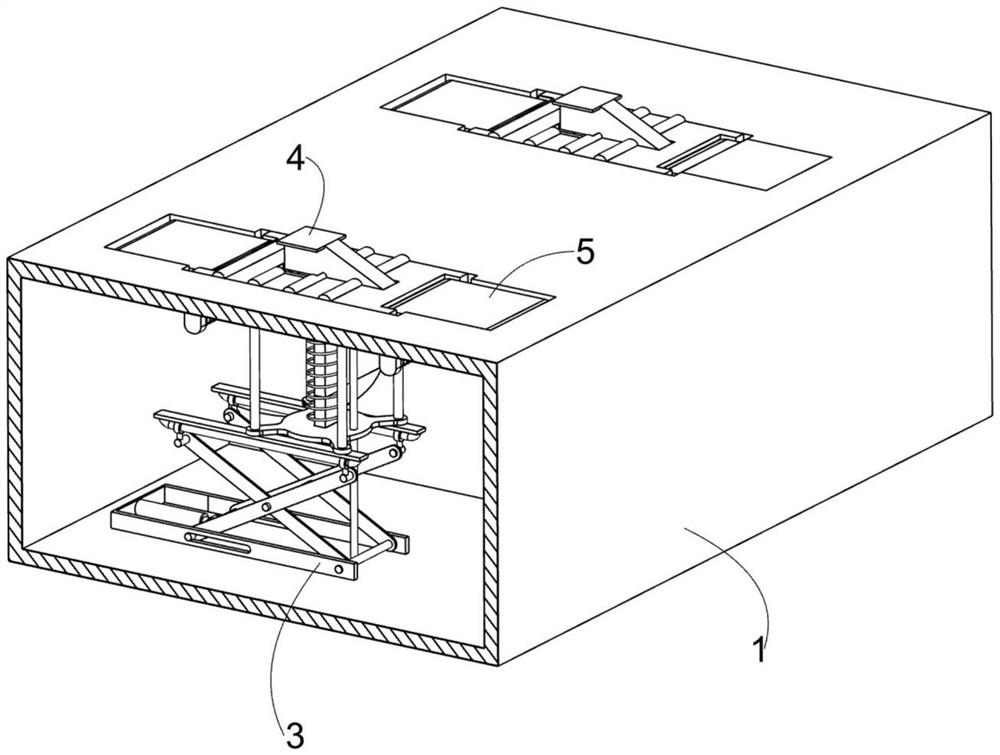
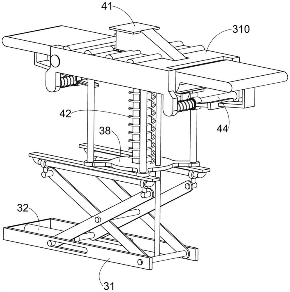
[0027] A vehicle lifting device for new energy battery replacement, such as Figure 1-8 As shown, it includes a lifting main body 1, a connecting plate 2, a lifting assembly 3, an extruding assembly 4, a limiting assembly 5, a fixed rod 6 and an extension plate 8, and a pair of connecting plates 2 are jointly supported on the two lifting main bodies 1 for The lifting assembly 3 for car lifting is symmetrically positioned in the lifting body 1, the extrusion assembly 4 is arranged on the lifting assembly 3, the extrusion assembly 4 is located in a lifting body 1, and the restriction assembly 5 for restricting the tire is of sliding type Connected to the extruding assembly 4 , the fixed rod 6 is symmetrically and fixedly connected in the lifting body 1 at the same place, and the extension plate 8 is arranged on the extruding assembly 4 .

[0028] Elevating assembly 3 comprises U-shaped frame 31, hydraulic cylinder 32, moving rod 33, lifting rod one 34, lifting rod two 35, movabl...

Embodiment 2

[0035] On the basis of Example 1, such as Figure 9-10 As shown, it also includes a positioning prompt assembly 7, the positioning prompt assembly 7 is arranged on a lifting body 1, and the positioning prompt assembly 7 is used to prompt the driver. , rack 73, rotating shaft 74, gear 75 and prompt pendulum plate 76, one side of lifting main body 1 side is fixedly installed with mounting bar 71, and lower pressing bar 72 is slidably connected on lifting main body 1 at the same place, and lower pressing bar 72 One end is fixedly connected with the lower part of the extrusion block 41, a rack 73 is welded on the lower pressing bar 72, and a rotating shaft 74 is rotatably connected to the top of the mounting bar 71 away from the lifting body 1, and a gear 75 is welded on the rotating shaft 74, and the gear 75 and The racks 73 are engaged with each other, and the rotating shaft 74 is fixedly connected with a prompting pendulum plate 76. The prompting pendulum plate 76 is written wi...


PUM


Abstract

The invention relates to the field of new energy automobile battery replacement, in particular to vehicle lifting equipment for new energy battery replacement, which comprises a lifting main body, a connecting plate, a lifting assembly, an extrusion assembly, a limiting assembly and the like, a pair of connecting plates are jointly supported on the two lifting bodies, the lifting assemblies are symmetrically positioned in the lifting bodies, the extrusion assemblies are arranged on the lifting assemblies and located in one lifting body, and the limiting assemblies are connected to the extrusion assemblies in a sliding mode. Through cooperation of the first lifting rod and the second lifting rod, the movable seat drives the guide plate and the device on the guide plate to move upwards, so that the lifting pad lifts the automobile, an old battery is disassembled, an external device replaces a fully charged new battery into the automobile, and the battery can be accurately installed in the automobile.

Description

technical field [0001] The invention relates to the field of new energy vehicle battery replacement, in particular to a vehicle lifting device for new energy battery replacement. Background technique [0002] New energy vehicles are appearing more and more frequently in front of people. The development of domestic new energy vehicles can be described as changing with each passing day. New energy vehicles refer to the use of unconventional vehicle fuels as power sources, and comprehensive vehicle power control and drive. Advanced technology, the formation of vehicles with advanced technical principles, new technologies, and new structures. The battery life of new energy vehicles generally ranges from 3 to 8 years. When the battery of new energy vehicles reaches the limit of use, it needs to be replaced Replacement battery. [0003] In the existing new energy vehicle battery replacement technology, the driver needs to drive the new energy vehicle into the new energy replaceme...

Claims


Application Information

Patent Timeline
Patent Type & Authority Applications(China)
IPC IPC(8): B60L53/80B60S5/06
CPCB60L53/80B60S5/06Y02T10/70Y02T10/7072
Inventor 熊武龙
Owner STATE GRID XINJIANG ELECTRIC POWER COMPANY HAMI POWER SUPPLY
Why Eureka
Try Eureka