A feeder for concrete processing

A concrete and feeder technology, applied in the direction of conveyor objects, transportation and packaging, packaging, etc., can solve the waste of manpower and other problems, achieve the effect of improving the cleaning effect, improving the scraping effect, and saving manpower

Active Publication Date: 2022-08-09
新兴栈(绵阳)建材有限公司
View PDF7 Cites 2 Cited by
  • Summary
  • Abstract
  • Description
  • Claims
  • Application Information

AI Technical Summary

Problems solved by technology

[0004] In view of the above-mentioned related technologies, the inventor believes that there are the following technical defects: when the concrete is transported, part of the concrete will adhere to the spiral body, which needs to be scraped manually, and a lot of manpower is wasted by manual scraping

Method used


Image

  • A feeder for concrete processing
  • A feeder for concrete processing
  • A feeder for concrete processing

Examples


Embodiment Construction

[0033] Attached to the following Figure 1-4 This application will be described in further detail.

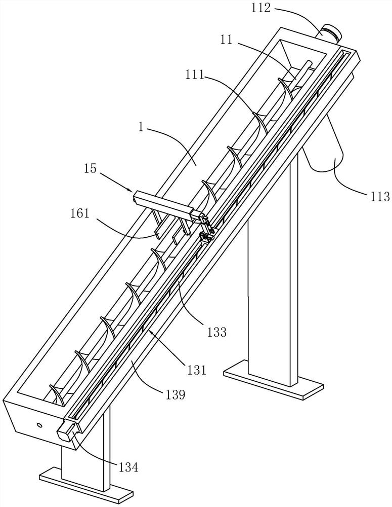
[0034] The embodiment of the present application discloses a feeder for concrete processing. refer to figure 1 , a feeder for concrete processing, comprising a casing 1, a rotating shaft 11 is arranged in the casing 1 along the length direction of the casing 1, and a screw blade 111 is fixed on the rotating shaft 11 along the length direction of the rotating shaft 11 One end of the casing 1 is fixedly provided with a drive motor 112 for driving the rotating shaft 11 to drive the helical blade 111 to rotate, and one end of the casing 1 is connected with the casing 1 and is provided with a discharge pipe 113 .

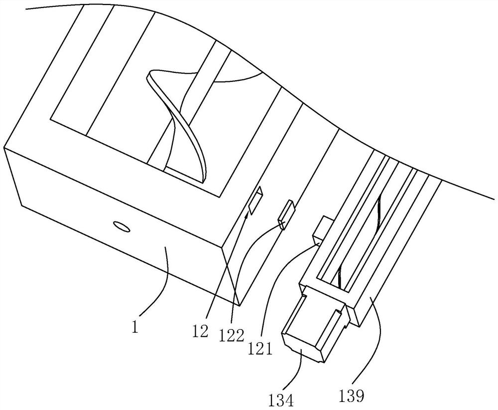
[0035] combine figure 1 and figure 2 , a rod body 139 is detachably connected to one side of the casing 1 along the length direction of the casing 1, and a plurality of slots 12 are opened on the surface of the casing 1 facing the rod body 139. The insert blocks 121...


PUM


Abstract

The present application relates to a feeder for concrete processing, comprising a casing, a rotating shaft is rotatably arranged in the casing, a helical blade is arranged on the rotating shaft, a drive motor is fixed at one end of the casing, and one end of the casing is connected to the casing. A discharge pipe is communicated and arranged, a rod body is detachably connected to one side of the casing along the length direction of the casing, a moving rod is slidably arranged on the rod body, and the end of the moving rod away from the rod body is provided with a connecting rod, and the connecting rod is set to be retractable Structure, the retractable structure includes a fixed rod and a sleeve sleeved and slidably connected to the fixed rod, the fixed rod is fixed on the moving rod, a spring is arranged in the connecting rod, and the surface of the sleeve facing the helical blade is provided with The scraper with the two surfaces of the spiral blades facing away from each other is abutted, and the rod body is provided with a moving device for driving the moving rod to move along the length direction of the rod body; the present application has the advantage of saving manpower for manual cleaning of the spiral blades.

Description

technical field [0001] The present application relates to the field of concrete processing, in particular to a feeder for concrete processing. Background technique [0002] A screw conveyor is a machine that uses a motor to drive a screw to rotate and push materials to achieve the purpose of conveying. It can be conveyed horizontally, obliquely or vertically, and has the advantages of simple structure, small cross-sectional area, good sealing, convenient operation, easy maintenance, and convenient closed transportation. [0003] The Chinese patent application publication number CN103818688A discloses a screw conveyor, including a frame, a driving mechanism, a conveying cylinder, a screw shaft, a screw body, a head drive bearing box and a tail drive bearing box, the frame supports the conveying drum, and the conveying drum There is an inlet and outlet on the upper part, and the driving mechanism drives the screw body in the conveying cylinder. The end of the conveying cylind...

Claims


Application Information

Patent Timeline
Patent Type & Authority Patents(China)
IPC IPC(8): B65G33/26B65G33/32B65G33/34B65G33/24B65G45/12
CPCB65G33/265B65G33/32B65G33/34B65G33/24B65G45/12
Inventor 韦成秋姚民红马快夏永州刘德刚程元都
Owner 新兴栈(绵阳)建材有限公司
Why Eureka
Try Eureka