Casting sand box
A technology of sand box and side plate, applied in the field of workpiece casting, can solve the problems of inability to guarantee product quality, high safety hazard, and heavy sand box weight, and achieve the effects of easy control of reverse deformation, weight reduction, and safety hazard reduction.
- Summary
- Abstract
- Description
- Claims
- Application Information
AI Technical Summary
Problems solved by technology
Method used
Image
Examples
Embodiment 1
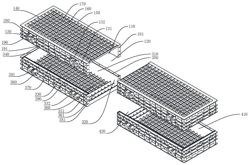
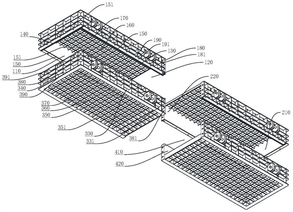
[0043] see Figure 1 to Figure 2 . A casting flask described in this embodiment includes a first upper flask, a second upper flask, a first lower flask and a second lower flask, and the top of the first upper flask is grid-shaped structure, the bottom of the first upper sand box is provided with a first opening 110, one end of the first upper sand box is provided with a second opening 120, the bottom of the first lower sand box is a grid structure, and the first lower sand box A third opening 310 is provided at the top of the first lower flask, a fourth opening 320 is provided at one end of the first lower flask, the top of the second upper flask is a grid structure, and the fifth opening is arranged at the bottom of the second upper flask 210, one end of the second upper sand box is provided with a sixth opening 220, the bottom of the second lower sand box is a grid structure, the top of the second lower sand box is provided with a seventh opening 410, the second lower sand ...
Embodiment 2
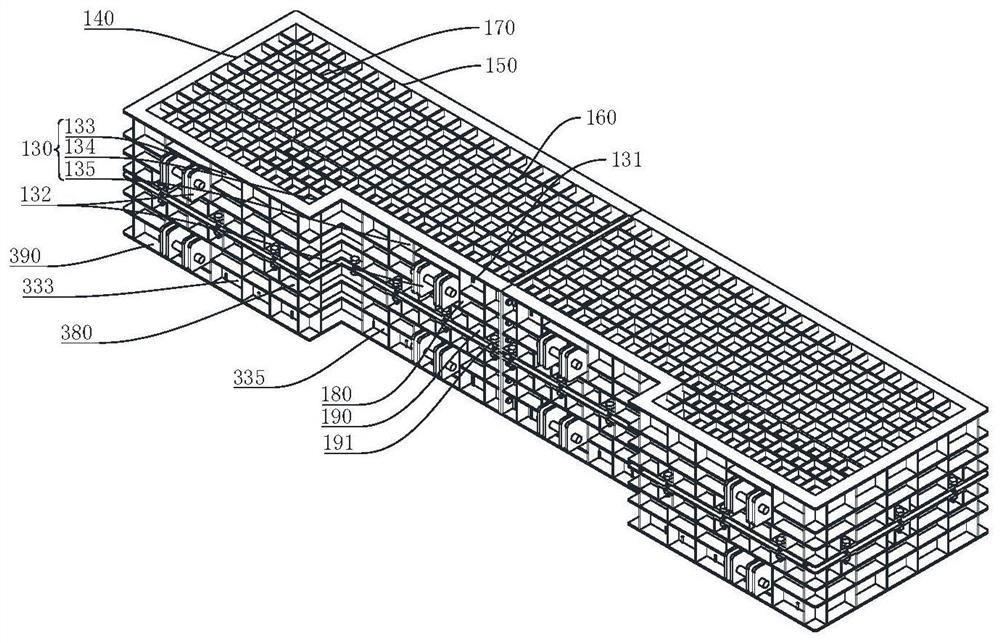
[0051] see image 3. A casting flask described in this embodiment includes a first upper flask, a second upper flask, a first lower flask and a second lower flask, and the top of the first upper flask is grid-shaped structure, the bottom of the first upper sand box is provided with a first opening 110, one end of the first upper sand box is provided with a second opening 120, the bottom of the first lower sand box is a grid structure, and the first lower sand box A third opening 310 is provided at the top of the first lower flask, a fourth opening 320 is provided at one end of the first lower flask, the top of the second upper flask is a grid structure, and the fifth opening is arranged at the bottom of the second upper flask 210, one end of the second upper sand box is provided with a sixth opening 220, the bottom of the second lower sand box is a grid structure, the top of the second lower sand box is provided with a seventh opening 410, the second lower sand box An eighth...
Embodiment 3
[0061] see Figure 4 to Figure 6 . A casting flask described in this embodiment includes a first upper flask, a second upper flask, a first lower flask and a second lower flask, and the top of the first upper flask is grid-shaped structure, the bottom of the first upper sand box is provided with a first opening 110, one end of the first upper sand box is provided with a second opening 120, the bottom of the first lower sand box is a grid structure, and the first lower sand box A third opening 310 is provided at the top of the first lower flask, a fourth opening 320 is provided at one end of the first lower flask, the top of the second upper flask is a grid structure, and the fifth opening is arranged at the bottom of the second upper flask 210, one end of the second upper sand box is provided with a sixth opening 220, the bottom of the second lower sand box is a grid structure, the top of the second lower sand box is provided with a seventh opening 410, the second lower sand ...
PUM
 Abstract
Description
Claims
Application Information
 - R&D
- Intellectual Property
- Life Sciences
- Materials
- Tech Scout
- Unparalleled Data Quality
- Higher Quality Content
- 60% Fewer Hallucinations
Browse by: Latest US Patents, China's latest patents, Technical Efficacy Thesaurus, Application Domain, Technology Topic, Popular Technical Reports.
© 2025 PatSnap. All rights reserved.Legal|Privacy policy|Modern Slavery Act Transparency Statement|Sitemap|About US| Contact US: help@patsnap.com


