
Workpiece machining conveying disc and workpiece machining conveying mechanism using workpiece machining conveying disc

A technology of conveying mechanism and conveying disc, which is applied in the direction of metal processing equipment, manufacturing tools, grinding machine parts, etc., to achieve effective adsorption effect

Active Publication Date: 2021-09-21
CHANGZHOU SHUJIE PLASTIC CO LTD
View PDF10 Cites 0 Cited by
  • Summary
  • Abstract
  • Description
  • Claims
  • Application Information

AI Technical Summary

Problems solved by technology

[0004] The first object of the present invention is to provide a workpiece processing conveying tray to solve the technical problem of completing the grinding of the surface of the workpiece during the process of conveying the workpiece and completing the removal of the powder particles generated by the grinding after grinding
[0005] The second object of the present invention is to provide a workpiece processing and conveying mechanism to solve the technical problem of completing the grinding of the surface of the workpiece during the process of conveying the workpiece and completing the removal of the powder particles generated by the grinding after grinding

Method used


Image

  • Workpiece machining conveying disc and workpiece machining conveying mechanism using workpiece machining conveying disc
  • Workpiece machining conveying disc and workpiece machining conveying mechanism using workpiece machining conveying disc
  • Workpiece machining conveying disc and workpiece machining conveying mechanism using workpiece machining conveying disc

Examples


Embodiment 1

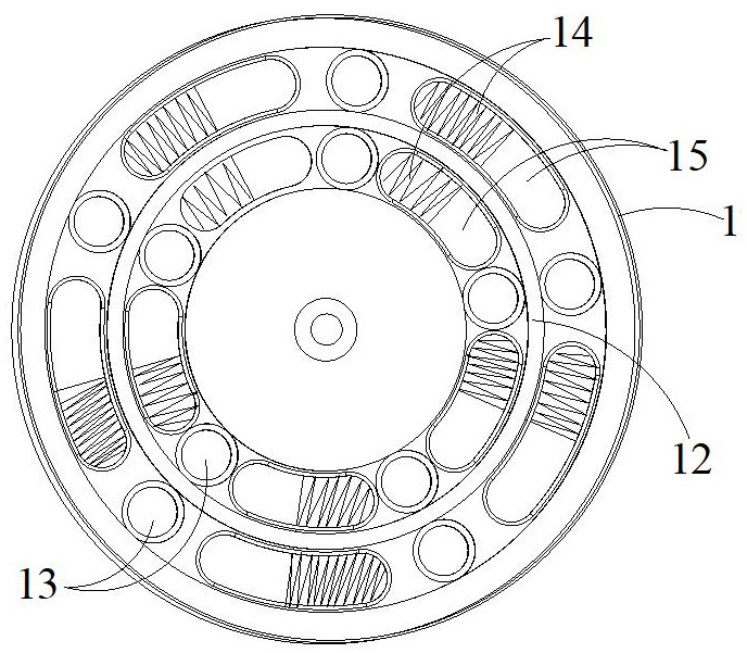
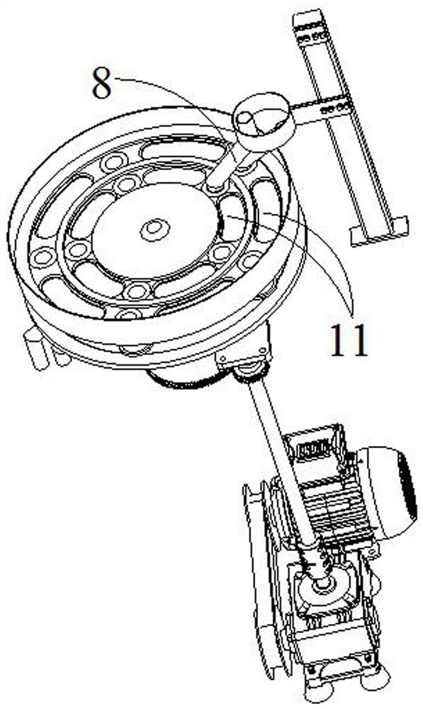
[0038] see Figure 1 to Figure 4 As shown, this embodiment provides a workpiece processing conveying tray, including: a disc-shaped processing disc 1 suitable for circular motion and at least one annular structure recessed on the disc-shaped processing disc 1 The processing and discharging unit; here, the processing and discharging unit is synchronously driven to perform circular motion during the circular motion of the disc-shaped processing disc 1, so that the workpiece 2 processed by the processing and discharging unit can be placed on the disc-shaped processing disc 1 The transfer of the workpiece 2 is realized during the circular motion.

[0039] The processing and discharging unit of this embodiment includes several concave arc-shaped processing tanks 11 distributed at intervals along the circumferential direction, and a through-disc-shaped processing tank provided between every two adjacent arc-shaped processing tanks 11. The discharge port 13 of the disc 1; that is to...

Embodiment 2

[0055] On the basis of the workpiece processing conveying tray in Embodiment 1, the workpiece processing conveying tray provided in this embodiment has the same general structure as that in Embodiment 1, except that in this embodiment, the grinding treatment structure provided in the grinding area 14 adopts, for example, But not limited to abrasive discs or sandpaper; and the adsorption treatment structure provided in the adsorption area 15 adopts paste paraffin. After the grinding treatment structure and the adsorption treatment structure are assembled in place in the arc-shaped treatment tank 11, the grinding treatment structure and the adsorption treatment structure at this time are flush with the end face of the workpiece 2 facing the discharge port 13, so that the workpiece 2 is polished and powdered. After the particle is adsorbed, it can smoothly enter the discharge port 13 along with the circular motion of the disc-shaped processing disc 1, without the situation that th...

Embodiment 3

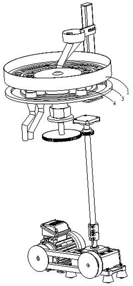
[0058] see Figure 1 to Figure 8 As shown, on the basis of the workpiece processing conveying plate in embodiment 1 or embodiment 2, this embodiment provides a workpiece processing conveying mechanism, including: the workpiece processing conveying plate in embodiment 1 or embodiment 2, and the disc The disc-shaped processing disc 1 is coaxially arranged on the disc-shaped discharge disc 3 below the disc-shaped process disc 1, and between the disc-shaped process disc 1 and the disc-shaped discharge disc 3 and the discharge port 13 one by one Corresponding feed pipe 4. It should be noted that the feed pipe 4 here is fixedly connected with the end face of the disc-shaped processing tray 1 facing the disc-shaped discharge tray 3, and the feed pipe 4 itself and the disc-shaped discharge tray 3 are in contact with each other. Fitting or direct non-contact but a small gap exists, because even a small gap will not affect the entry of the workpiece 2 into the discharge port 13, which ...


PUM


Abstract

The invention discloses a workpiece machining conveying disc and a workpiece machining conveying mechanism using the workpiece machining conveying disc. The workpiece machining conveying disc comprises a disc-shaped treatment disc suitable for doing the circular motion and at least one machining discharging unit, wherein the machining discharging units are arranged on the disc-shaped treatment disc in a sunken mode and are of an annular structure. Each machining discharging unit comprises a plurality of sunken arc-shaped treatment grooves and discharging openings, wherein the arc-shaped treatment grooves are distributed at intervals in the circumferential direction, and each discharging opening is formed between the two corresponding and adjacent arc-shaped treatment grooves and penetrates through the disc-shaped treatment disc. Each arc-shaped treatment groove comprises a polishing area and an adsorption area, wherein each polishing area and the corresponding adsorption area are adjacently arranged. When the disc-shaped treatment disc does the circular motion, a workpiece corresponding to each arc-shaped treatment groove is sequentially treated by the corresponding polishing area and the corresponding adsorption area and then is discharged from the corresponding discharging opening. According to the workpiece machining conveying disc, polishing of the surfaces of the workpieces can be accomplished in the workpiece conveying process, and removal of powder particles generated by polishing can be accomplished after polishing is conducted.

Description

technical field [0001] The invention relates to the technical field of mechanical processing, in particular to a workpiece processing conveying plate and a workpiece processing conveying mechanism using the same. Background technique [0002] Some parts in the chemical material adding barrel (hereinafter referred to as the workpiece) are inseparable from the operation of grinding and paraffin coating to protect some parts during the processing process. Only after the outer surface is polished can they be assembled into the chemical material adding in the barrel. Grinding is a kind of surface modification technology. It generally refers to a processing method that uses rough objects (sandpaper with higher hardness particles, etc.) to change the physical properties of the material surface through friction. The main purpose is to obtain a specific surface roughness. [0003] For the above-mentioned workpieces that have been polished, there will be powder particles that have be...

Claims


Application Information

Patent Timeline
Patent Type & Authority Applications(China)
IPC IPC(8): B24B41/00B24B55/06
CPCB24B41/005B24B55/06
Inventor 包敦士王云梦季建萍
Owner CHANGZHOU SHUJIE PLASTIC CO LTD
Learn More