Intelligent full-automatic research ward housekeeper robot
A fully automatic and robotic technology, applied in the field of intelligent robots, which can solve the problems of low degree of intelligence, no countdown function, and inconvenience in actual use.
- Summary
- Abstract
- Description
- Claims
- Application Information
AI Technical Summary
Problems solved by technology
Method used
Image

Examples
Embodiment 1
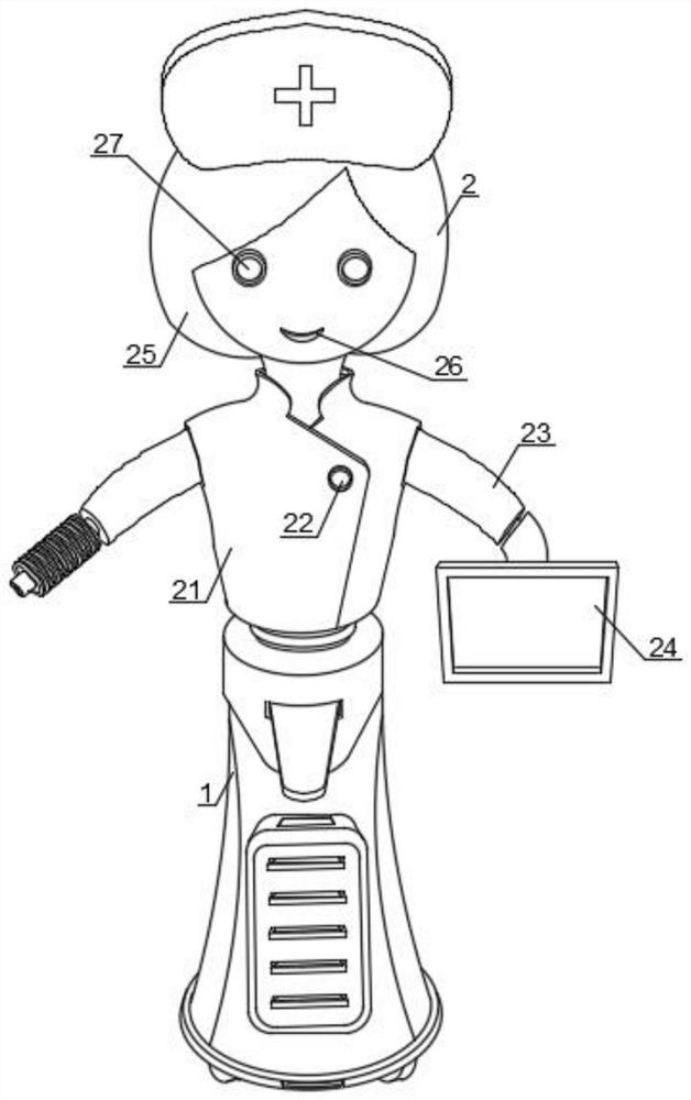
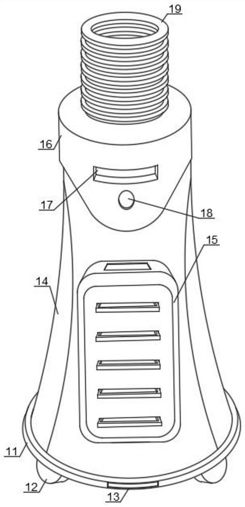
[0048] refer to Figure 1-3 , an intelligent fully automatic research ward housekeeper robot, including a support column 1, an auxiliary mechanism 2 and a system assembly 3, the support column 1 includes a support chassis 11, moving wheels 12, a scanning mechanism 13, a cylinder body 14, and an auxiliary box 15 , top cover 16, detection mechanism 17, sound receiving mechanism 18 and angle adjustment shaft 19 are installed, four groups of moving wheels 12 are installed on the bottom end of support chassis 11, scanning mechanism 13 is offered on the front end of support chassis 11, and the top of support chassis 11 Cylinder 14 is installed, the front of cylinder 14 is provided with auxiliary box 15, and the top of cylinder 14 offers installation top cover 16, and the front end of installation top cover 16 offers detection mechanism 17, and the sound receiving mechanism 18 is installed below detection mechanism 17, installs top The top of the cover 16 is equipped with an angle ad...
Embodiment 2
[0050] refer to Figure 4 and 5 The contact arm 236 includes an arm 2361, an air bag 2362 and an interconnection interface 2363. The outer ring of the arm 2361 is wrapped with an inflatable bag 2362, and the middle of the outer end of the arm 2361 is provided with an interconnection interface 2363, which can be connected to another through the interconnection interface 2363. The robot is interconnected and can summarize the patient's data and then export it. The overall device can be adjusted by adjusting the angle of the shaft 19 to form a maximum angle of 90 degrees between the support vertical tube 1 and the auxiliary mechanism 2. Remove the signature plate 24 and place it on the charging unit. Inflate the inner cavity of the airbag 2362 so that the entire bottom of the inflatable bag 2362 touches the hospital bed. The patient supports the back and thighs with the contact arm 236 as the fulcrum, adjusts the angle adjustment shaft 19 to the quasi-working state, and adjusts t...
Embodiment 3
[0052] refer to Figure 6 , system assembly 3 includes:
[0053] Receiving terminal 31: used for information reception of regional operations, capturing dynamic images of users, collecting images with lenses, and then transmitting data to receiving terminal 31, which processes the data and transmits the processed data into the receiving terminal. Terminal 31, so as to perform face recognition and sign-in for personnel, and the setting angle of the signature board 24 is inclined downward by 30 degrees, which is convenient for bedridden patients to sign;
PUM
 Abstract
Description
Claims
Application Information
 - R&D
- Intellectual Property
- Life Sciences
- Materials
- Tech Scout
- Unparalleled Data Quality
- Higher Quality Content
- 60% Fewer Hallucinations
Browse by: Latest US Patents, China's latest patents, Technical Efficacy Thesaurus, Application Domain, Technology Topic, Popular Technical Reports.
© 2025 PatSnap. All rights reserved.Legal|Privacy policy|Modern Slavery Act Transparency Statement|Sitemap|About US| Contact US: help@patsnap.com