
Section steel support and cover plate fabricated foundation for a frozen earth area.

A prefabricated, profiled steel technology, applied in infrastructure engineering, construction, etc., can solve the problems of large friction coefficient of concrete surface, limited bottom area of ​​support section, displacement of concrete slats, etc., and achieve low surface friction coefficient and large inclination angle. , the effect of easy transportation and assembly

Active Publication Date: 2021-09-21
四川电力设计咨询有限责任公司
View PDF26 Cites 0 Cited by
  • Summary
  • Abstract
  • Description
  • Claims
  • Application Information

AI Technical Summary

Problems solved by technology

This method solves the problem of quick assembly of foundations in permafrost areas to a certain extent, but there are still some defects. First, although the support section with a hollow section can reduce the weight of the components to a certain extent, the support section of the concrete structure, It still has a large volume and weight, and it is inconvenient to transport and install. Second, the support section of the concrete structure has a limited bottom area, and its load transmission is mainly concentrated in the middle area of ​​the bottom plate. However, since the bottom of the base is composed of multiple concrete slats, there may still be problems such as displacement of the concrete slats due to uneven force
Third, although the conical column of the concrete structure can reduce the surface frost heaving force, due to the large friction coefficient of the concrete surface, it will still be affected to a certain extent, so that the foundation is subjected to part of the surface frost heaving force

Method used


Image

  • Section steel support and cover plate fabricated foundation for a frozen earth area.
  • Section steel support and cover plate fabricated foundation for a frozen earth area.

Examples


Embodiment Construction

[0019] The present invention is further described below.

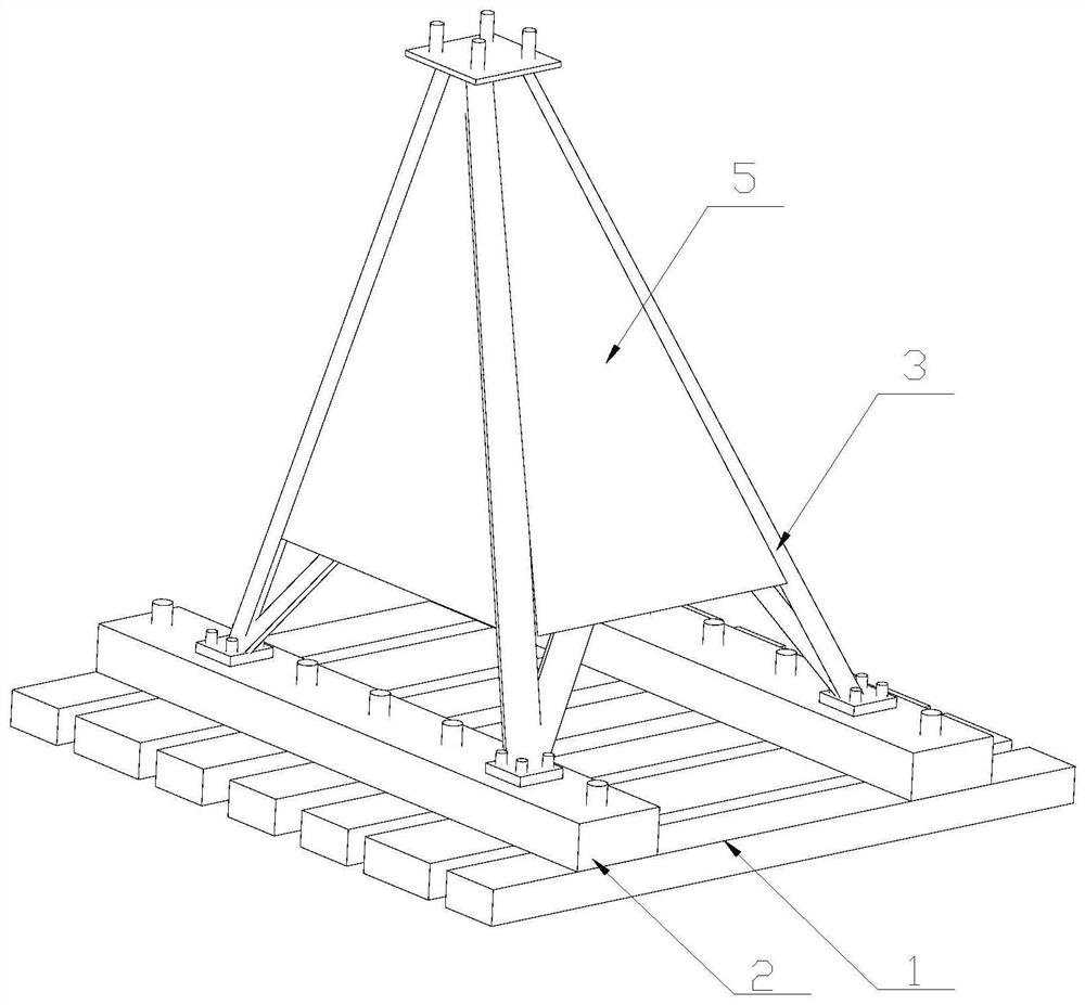
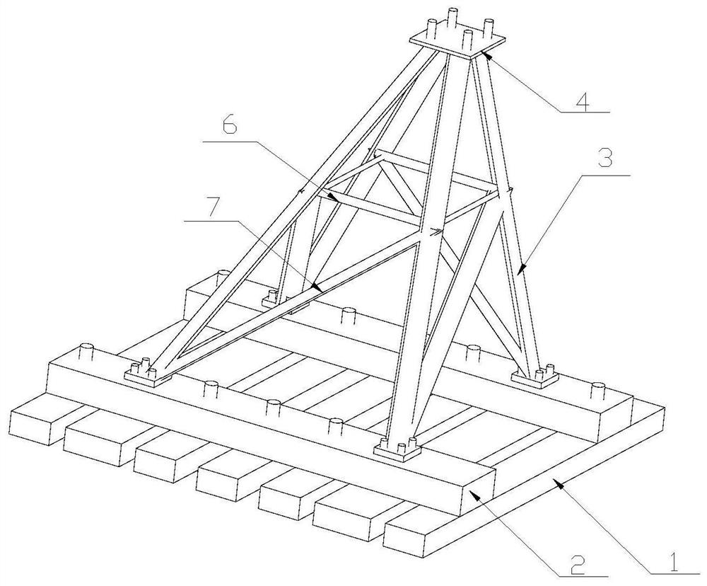
[0020] The assembled foundation for the sectioned steel support cladding plate in the permafrost area disclosed by the present invention includes a base plate slat 1 and a base plate connecting beam 2, a plurality of the base plate slats 1 are arranged in parallel, and the base plate connecting beam 2 is vertically connected to the base plate On the slat 1, the bottom plate connecting crossbeam 2 is provided with a shaped steel bracket, the shaped steel bracket includes at least three main materials 3, and each main material 3 forms an oblique cone structure, and the bottom of the main materials 3 of the shaped steel bracket is dispersedly connected On the connecting beam 2 of the bottom plate, the top of the main material 3 of the shaped steel bracket is converged and connected with the connecting seat plate 4 for connecting the foot plate of the iron tower. The surface friction coefficients of the steel bracket and t...


PUM


Abstract

The invention relates to the field of electric power facilities, and discloses a section steel support and cover plate fabricated foundation for a frozen earth area. The foundation comprises bottom plate battens and a bottom plate connecting cross beam, the bottom plate battens are arranged in parallel, the bottom plate connecting cross beam is perpendicularly connected to the bottom plate battens, the bottom plate connecting cross beam is provided with a section steel support, the section steel support comprises at least three main materials, and the main materials form a conical structure. The bottoms of the main materials of the section steel support are connected to the bottom plate connecting cross beam in a scattered manner, the tops of the main materials of the section steel support converge and are connected with a connecting base plate used for being connected with an iron tower foot plate, and a cover plate is arranged at the periphery of the section steel support to form a conical structure with the periphery closed. The surface friction coefficient of the section steel support and the surface friction coefficient of the cover plate are both smaller than the surface friction coefficient of concrete. By the adoption of the foundation, frost heaving force generated by frozen soil on the foundation can be reduced, the construction period is short, and the stress performance is better.

Description

technical field [0001] The invention relates to the field of electric power facilities, in particular to an assembled foundation of shaped steel bracket cladding plates used in permafrost regions. Background technique [0002] With the increase of national electric power construction scale, there are more and more power transmission lines in permafrost areas with lower temperature. During the freezing process, permafrost will generate frost heave force on buildings, which can be divided into tangential freezing force according to its action direction. Expansion force, normal frost heave force and vertical frost heave force, vertical frost heave force and tangential frost heave force can greatly reduce the uplift bearing capacity of the foundation, which must be considered in the foundation design of transmission lines and also has a greater impact Geological action. At present, the foundations used in permafrost areas are mainly straight column slab foundations, pile founda...

Claims


Application Information

Patent Timeline
IPC IPC(8): E02D27/42E02D27/35
CPCE02D27/42E02D27/35
Inventor 郭艳军刘泉吴数伟田峻赵庆斌于强
Owner 四川电力设计咨询有限责任公司
Learn More