Supercharge Your Innovation With Domain-Expert AI Agents!

Optical system, camera module, electronic equipment and carrier

A technology of optical systems and electronic equipment, applied in the field of optical systems, can solve problems such as low imaging resolution and inability to meet people's use needs

Active Publication Date: 2021-09-21
JIANGXI JINGCHAO OPTICAL CO LTD
View PDF10 Cites 1 Cited by
  • Summary
  • Abstract
  • Description
  • Claims
  • Application Information

AI Technical Summary

Problems solved by technology

[0003] However, the imaging resolution of the camera module in the related art is still low in night and other low-light environments, which cannot meet the needs of people.

Method used


Image

  • Optical system, camera module, electronic equipment and carrier
  • Optical system, camera module, electronic equipment and carrier
  • Optical system, camera module, electronic equipment and carrier

Examples


specific Embodiment 1

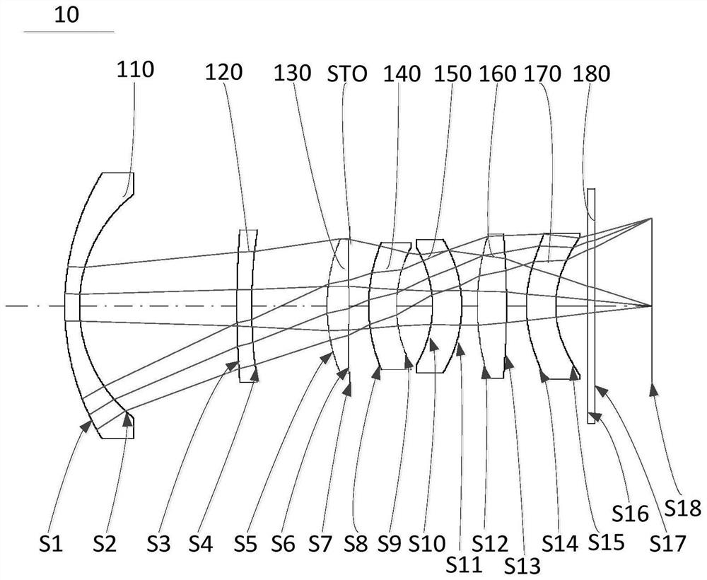
[0090] For a schematic structural view of the optical system 10 of the embodiment of the present application, see figure 1 , the optical system 10 includes a first lens 110, a second lens 120, a third lens 130, an aperture STO, a fourth lens 140, a fifth lens 150, and a sixth lens 160 arranged in sequence along the optical axis from the object side to the image side , the seventh lens 170 and the filter 180. The first lens 110 has a negative refractive power, the second lens 120 has a positive refractive power, the third lens 130 has a positive refractive power, the fourth lens 140 has a negative refractive power, the fifth lens 150 has a negative refractive power, and the sixth lens 160 has a negative refractive power. Positive refractive power, the seventh lens 170 has positive refractive power. The object side S1 of the first lens 110 is convex at the near optical axis, and the image side S2 of the first lens 110 is concave at the near optical axis. The object side S3 of ...

specific Embodiment 2

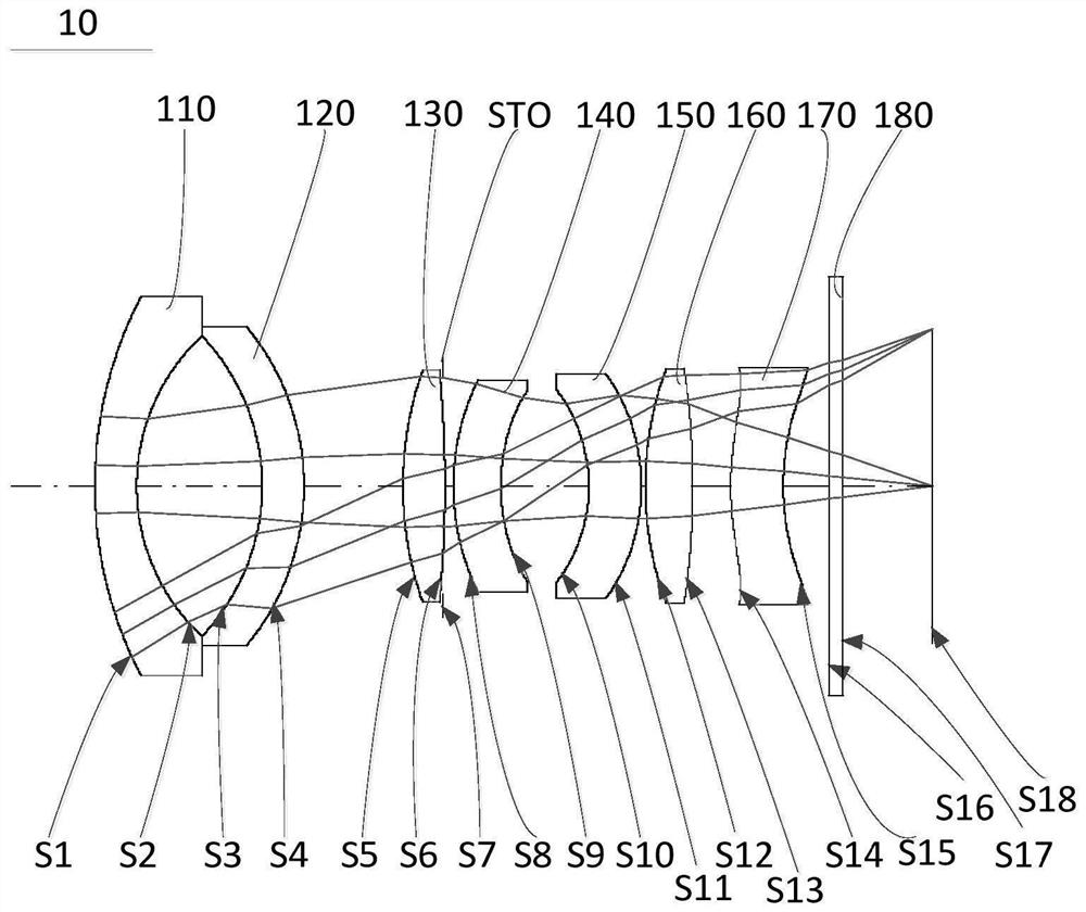
[0105] For a schematic structural view of the optical system 10 of the embodiment of the present application, see image 3 , the optical system 10 includes a first lens 110, a second lens 120, a third lens 130, an aperture STO, a fourth lens 140, a fifth lens 150, and a sixth lens 160 arranged in sequence along the optical axis from the object side to the image side , the seventh lens 170 and the filter 180. The first lens 110 has a negative refractive power, the second lens 120 has a negative refractive power, the third lens 130 has a positive refractive power, the fourth lens 140 has a positive refractive power, the fifth lens 150 has a negative refractive power, and the sixth lens 160 has a positive refractive power. Positive refractive power, the seventh lens 170 has negative refractive power. The object side S1 of the first lens 110 is convex at the near optical axis, and the image side S2 of the first lens 110 is concave at the near optical axis. The object side S3 of ...

specific Embodiment 3

[0120] For a schematic structural view of the optical system 10 of the embodiment of the present application, see Figure 5 , the optical system 10 includes a first lens 110, a second lens 120, a third lens 130, an aperture STO, a fourth lens 140, a fifth lens 150, and a sixth lens 160 arranged in sequence along the optical axis from the object side to the image side , the seventh lens 170 and the filter 180. The first lens 110 has a negative refractive power, the second lens 120 has a negative refractive power, the third lens 130 has a positive refractive power, the fourth lens 140 has a negative refractive power, the fifth lens 150 has a negative refractive power, and the sixth lens 160 has a negative refractive power. Positive refractive power, the seventh lens 170 has positive refractive power. The object side S1 of the first lens 110 is convex at the near optical axis, and the image side S2 of the first lens 110 is concave at the near optical axis. The object side S3 of...


PUM


Abstract

The embodiment of the invention discloses an optical system, a camera module, electronic equipment and a carrier. The optical system sequentially comprises a first lens, a second lens, a third lens, a fourth lens, a fifth lens, a sixth lens and a seventh lens from an object side to an image side along an optical axis. The optical system satisfies the following conditional expressions: 1.5 < Y1 / EPD < 3.4, wherein Y1 is the maximum optical effective diameter of the object side surface of the first lens, and EPD is the entrance pupil diameter of the optical system. According to the embodiment of the invention, through reasonable combination design of the refractive power and the surface type of the seven lenses, the optical system can meet the characteristic of a large aperture, sufficient light flux can be obtained, clearer and three-dimensional pictures can be shot at night and other environments with insufficient light, and the resolution of the optical system is improved.

Description

technical field [0001] The present application relates to the technical field of optical systems, in particular to an optical system, a camera module and electronic equipment. Background technique [0002] In recent years, with the continuous development of science and technology, portable electronic devices such as smart phones and tablet computers have become an indispensable part of people's lives, and the camera modules mounted on electronic devices are also becoming more and more diverse. [0003] However, the imaging resolution of the camera module in the related art is still low in nighttime and other low-light environments, which cannot meet the needs of people. Contents of the invention [0004] The embodiment of the present application provides an optical system, a camera module and an electronic device. Through the reasonable combination design of the refractive power and surface shape of seven lenses, the optical system can meet the characteristics of a large a...

Claims


Application Information

Patent Timeline
Patent Type & Authority Applications(China)
IPC IPC(8): G02B13/00G02B13/18
CPCG02B13/0015G02B13/0045G03B30/00
Inventor 谢晗李明
Owner JIANGXI JINGCHAO OPTICAL CO LTD
Features
  • R&D
  • Intellectual Property
  • Life Sciences
  • Materials
  • Tech Scout
  • Unparalleled Data Quality
  • Higher Quality Content
  • 60% Fewer Hallucinations
Learn More