Safety fireproof communication equipment cabinet

A communication equipment and safety technology, applied in electrical equipment shell/cabinet/drawer, electrical equipment structural parts, cooling/ventilation/heating renovation, etc., can solve the problems of large heat dissipation requirements, inconvenient cleaning and collection, etc.

Pending Publication Date: 2021-09-21
郑焕彬
View PDF0 Cites 0 Cited by
  • Summary
  • Abstract
  • Description
  • Claims
  • Application Information

AI Technical Summary

Problems solved by technology

[0003] The existing technology has the following disadvantages: due to the environment in which the equipment cabinet is located and the frequency of use, the heat dissipation requirements of the equipment are very large. The cooling box on the side of the equipment cabinet usually uses a cooling fan to convert the internal hot air to the outside. There will be dust constantly attached to the filter at the front end, which is inconvenient and quick to clean and collect

Method used


Image

  • Safety fireproof communication equipment cabinet
  • Safety fireproof communication equipment cabinet
  • Safety fireproof communication equipment cabinet

Examples


no. 1 example

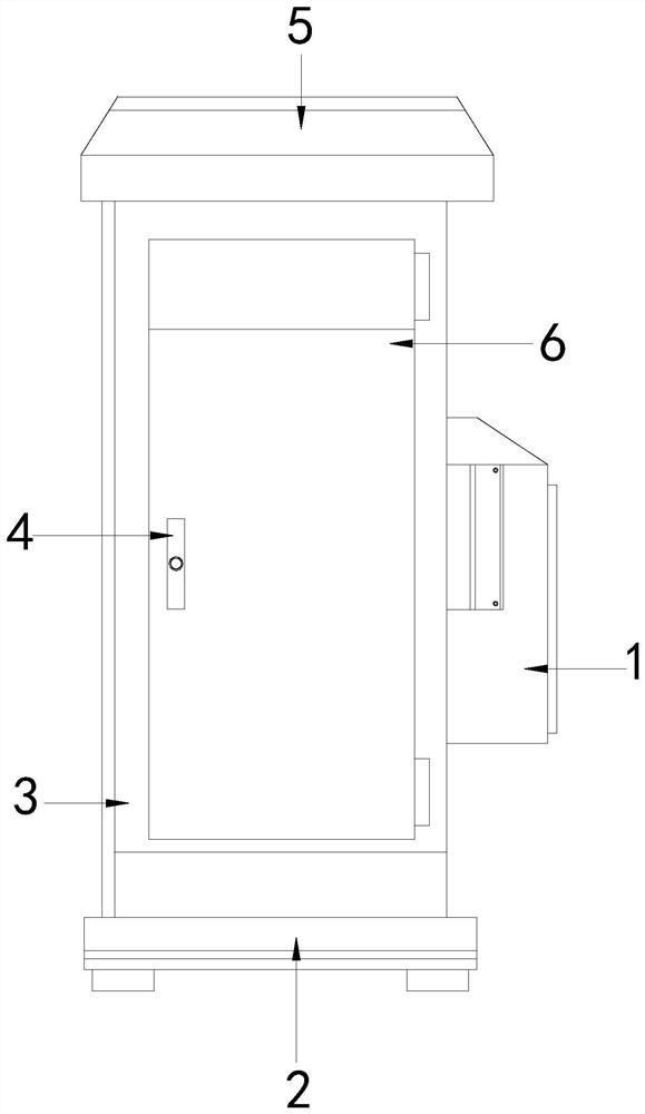
[0026] see Figure 1-Figure 3 , the present invention provides a technical solution for a safe and fireproof communication equipment cabinet: its structure includes: a heat dissipation box device 1, a support base 2, a main cabinet body 3, a door lock 4, an upper cover warehouse 5, and a movable door body 6, and the upper cover The warehouse 5 is installed above the main cabinet body 3 and is locked with the main cabinet body 3. A support base 2 is provided below the main cabinet body 3. The support base 2 is welded to the main cabinet body 3. The front of the main cabinet body 3 is The side is provided with a movable door body 6, and the movable door body 6 is buckled with the main cabinet body 3, and the side of the main cabinet body 3 is provided with a door lock 4, and the door lock 4 is buckled with the main cabinet body 3, so that The right side of the main cabinet body 3 is provided with a cooling box device 1, the cooling box device 1 is locked with the main cabinet bo...

no. 2 example

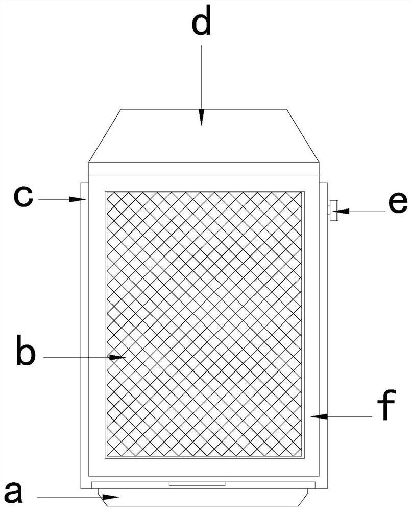
[0030] see Figure 4-Figure 6 , the present invention provides a technical solution for a safe and fireproof communication equipment cabinet: its structure includes: the scraper device e includes a contact shaft tube e1, an inner shaft rod e2, a slide bar group e3, a slider plate e4, and a side support device e5, The slider group e3 is installed on the outside of the slider plate e4 and fastened with the slider plate e4. The slider plate e4 is flexibly connected to the contact shaft tube e1 through the inner shaft rod e2. The left end of the contact shaft tube e1 is provided with The side support device e5, the side support device e5 is fastened with the contact shaft tube e1.

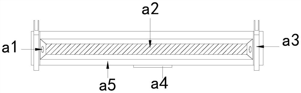
[0031] The contact shaft tube e1 includes a support tube e11, an inner hollow groove e12, a buffer collar e13, and a contact sleeve e14. A support tube e11 is provided inside the ring e13, and an inner hollow groove e12 runs through the inside of the support tube e11.

[0032] The side support device...


PUM


Abstract

The invention discloses a safety fireproof communication equipment cabinet which structurally comprises a heat dissipation box device, a supporting base, a main cabinet body, a door lock, an upper cover bin and a movable door body, wherein the upper cover bin is installed above the main cabinet body and connected with the main cabinet body in a locked mode. When equipment is used, through the arranged mechanisms, the problem that a heat dissipation box on the side edge of the equipment cabinet usually utilizes a heat dissipation fan to convert internal hot air to the outside, dust is continuously attached to a filter screen at the front end in the process, and cleaning and collection are inconvenient and fast can be solved; the equipment is matched with a sliding block plate through an arranged sliding rod set, then a contact shaft pipe is driven to do displacement motion along the filter screen, at the moment, extrusion contact can be formed on the inner surface of the filter screen through a special contact shaft tube structure, then dust attached to the surface of the filter screen is scraped off, a side supporting device is used for assisting reset fit, and finally rapid collection treatment is conducted through a collecting tank device, so that more convenience is achieved.

Description

technical field [0001] The invention is a safe and fireproof communication equipment cabinet, which belongs to the field of communication equipment. Background technique [0002] The communication chassis cabinet refers to the chassis cabinet used in communication. This type of product is mainly a chassis chassis processed by sheet metal equipment. It is more convenient for information transmission by loading some communication facilities inside. The equipment cabinet The body has sufficient impact resistance to damage without repair and normal use, and has the functions of heat insulation, airtightness, durability, fire prevention, and earthquake resistance. [0003] The existing technology has the following disadvantages: due to the environment in which the equipment cabinet is located and the frequency of use, the heat dissipation requirements of the equipment are very large. The cooling box on the side of the equipment cabinet usually uses a cooling fan to convert the in...

Claims


Application Information

Patent Timeline
Patent Type & Authority Applications(China)
IPC IPC(8): H05K5/00H05K5/02H05K7/20B01D46/00
CPCH05K5/0004H05K5/0213H05K5/0217H05K7/20181
Inventor 郑焕彬
Owner 郑焕彬
Why Eureka
Try Eureka