Method for producing a traction battery of a motor vehicle

A technology for traction batteries and automobiles, applied to batteries, electric vehicles, secondary batteries, etc., to reduce or limit the installation force

Pending Publication Date: 2021-09-21
LISA DRAXLMAIER GMBH
View PDF9 Cites 0 Cited by
  • Summary
  • Abstract
  • Description
  • Claims
  • Application Information

AI Technical Summary

Problems solved by technology

this is disadvantageous

Method used


Image

  • Method for producing a traction battery of a motor vehicle
  • Method for producing a traction battery of a motor vehicle
  • Method for producing a traction battery of a motor vehicle

Examples


Embodiment Construction

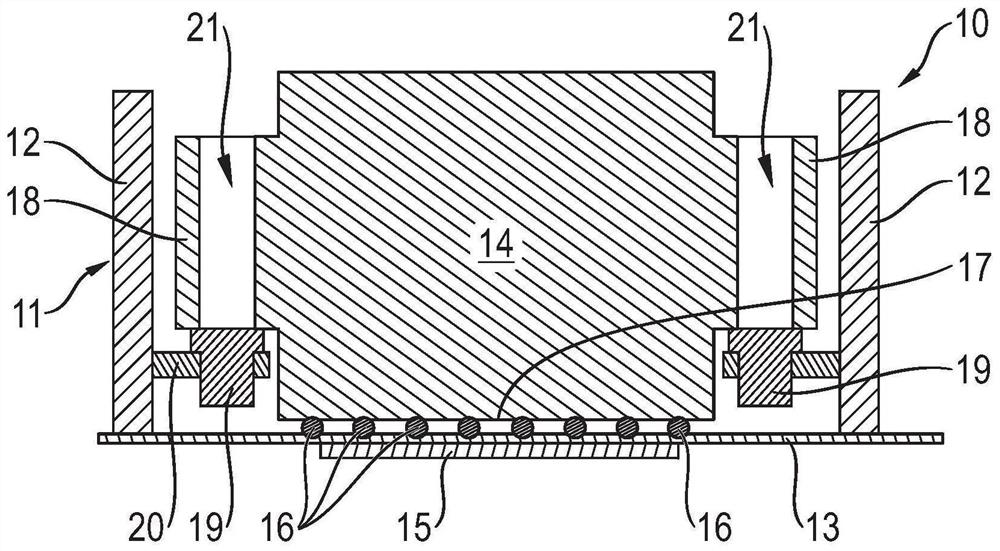
[0024] figure 1 It is a schematic partial cross-sectional view of a traction battery 10 of a motor vehicle. The traction battery 10 has a housing 11 formed from side walls 12 and a bottom wall 13 . Additionally, the housing can have figure 1 Top wall or cover not shown.

[0025] The housing has a plurality of receiving areas for the battery modules 14, wherein, for the sake of clarity, in figure 1 Only one such receiving chamber is shown in FIG. 2 , in which a battery module 14 is installed. The receiving area is at least partially delimited by side walls 12 and a bottom wall 13 .

[0026] The bottom wall 13 of the housing 11 of the traction battery 10 is a cooled bottom wall 13 , wherein figure 1 A cooling device 15 for cooling the bottom wall 13 is shown very schematically. Typically, the bottom wall 13 is flowed through by the coolant and thus has flow channels for the coolant. In this case, the cooling channels through which the coolant flows then form the cooling m...


PUM


Abstract

Method for producing a traction battery of a motor vehicle, wherein the traction battery (10) comprises a housing (11) and a plurality of battery modules (14) accommodated in the housing (11), and wherein a pasty heat-conducting compound (16) for thermally coupling the battery modules (14) with a cooled housing wall (13) of the housing (11) is arranged between the battery modules (14) and the cooled housing wall (13), having the following steps of: providing the housing (11) and the battery modules (14), measuring at least one portion of the particular battery module (14) and/or at least one portion of the housing (11), determining an actual gap between the battery module (14) and the cooled housing wall (13) depending on the measurement, determining an amount of heat-conducting compound (16) depending on the determined actual gap, applying the determined amount of heat-conducting compound (16) to the cooled housing wall (13) and/or the particular battery module (14), inserting the particular battery module (14) into the housing (11) with a defined insertion force, with heat-conducting compound (16) being distributed between the particular battery module (14) and the cooled housing wall (13) of the housing (11).

Description

technical field [0001] The invention relates here to a method for producing a traction battery for a motor vehicle. Background technique [0002] A traction battery of a vehicle has a housing and a plurality of battery modules. In order to cool the battery modules, it is known that the housing of the traction battery has cooled housing walls. The cooled housing wall has, in particular, coolant channels through which coolant flows. In order to enable efficient heat transfer from the battery modules to the cooled housing wall, it is known to arrange a pasty heat-conducting substance between the battery modules and the cooled housing wall. [0003] A traction battery is known from DE 10 2016 001 145 A1 with a battery housing and battery modules accommodated in the battery housing, wherein the battery housing comprises both a cooled bottom wall and a cooled top wall. wall. [0004] A battery assembly with a plurality of battery modules is known from US 2016 / 0268657 A1, in wh...

Claims


Application Information

Patent Timeline
Patent Type & Authority Applications(China)
IPC IPC(8): H01M50/249H01M10/04H01M10/653H01M10/613H01M50/204H01M50/244H01M50/262
CPCH01M10/653H01M10/613Y02T10/70Y02E60/10H01M10/6554H01M2220/20H01M10/6556H01M50/24Y02P70/50H01M50/204H01M50/249H01M50/244H01M50/262
Inventor 罗伯特·马格尼克里斯托夫·里斯特迈克尔·罗麦斯伯格斯特凡·塞德尔米歇尔·厄里希特菲利克斯·布雷德克阿米·斯特克马库斯·格瑞夫
Owner LISA DRAXLMAIER GMBH
Why Eureka
Try Eureka