Assembly and method suitable for sputtering ring batch electron beam welding
A technology of electron beam welding and vacuum electron beam welding, which is applied in the field of magnetron sputtering, can solve the problems of low vacuum electron beam welding efficiency, save multiple times of vacuuming and cooling time, improve production efficiency, and combine conveniently and flexibly Effect
- Summary
- Abstract
- Description
- Claims
- Application Information
AI Technical Summary
Problems solved by technology
Method used
Image

Examples
Embodiment 1
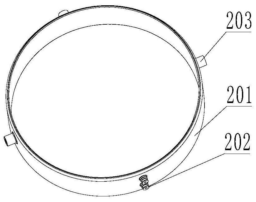
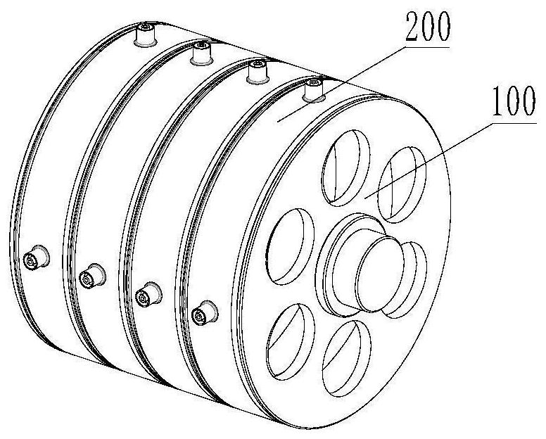
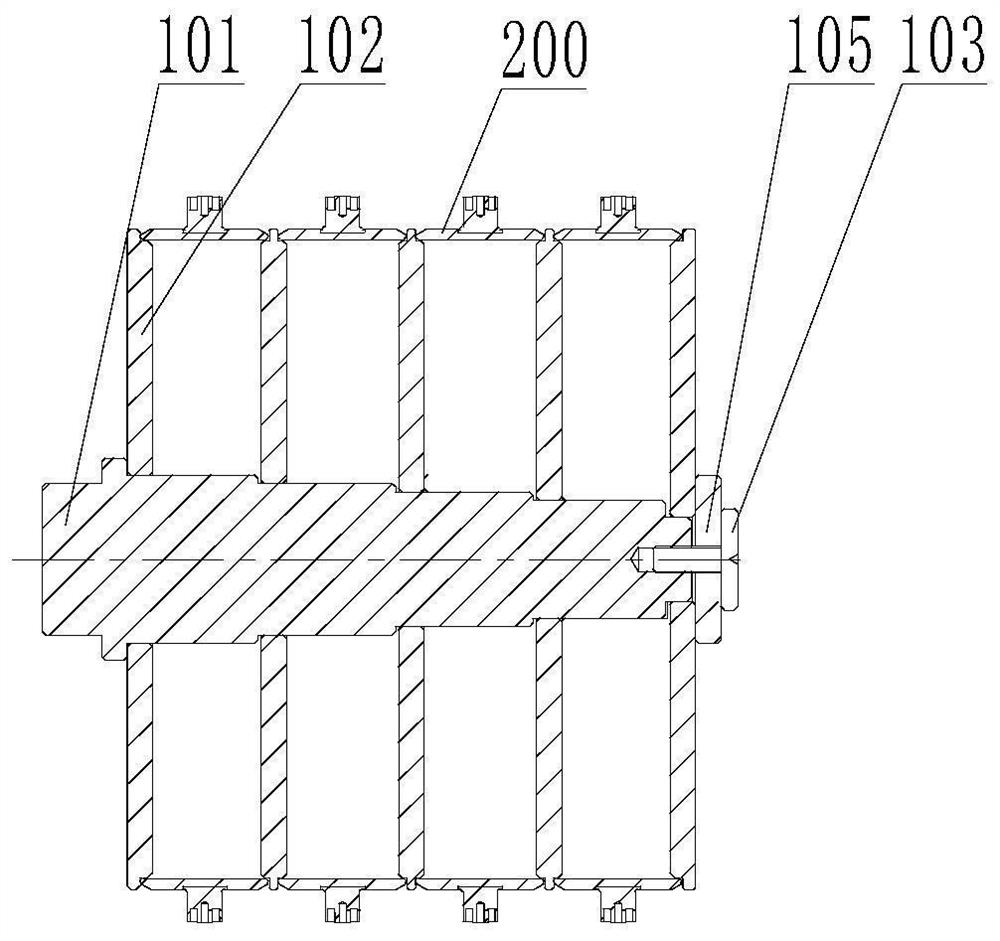
[0030] Such as image 3 Shown is a schematic diagram of the assembly when welding a four-piece sputtering ring. After the mandrel 101 is fixed on the chuck of the vacuum electron beam welding machine and adjusted, a separator 102 is first installed on the mandrel 101, and then the sputtering ring 200 and the separator 102 are installed in sequence, and a total of 4 times of sputtering are installed. Ring 200, partition 102, and finally install the baffle 105 behind the last partition, adjust the relative positions of the supports 203 and electrodes 202 of the four sputtering rings 200, so that the supports 203 of the four sputtering rings 200 are in parallel On the same straight line of the center line of the mandrel, the electrodes 202 of the four sputtering rings 200 are located on the same line parallel to the center line of the mandrel, and the bolts 103 are tightened to push the apex on the vacuum electron beam welding machine table to the bolts 103 , so that the sputter...
Embodiment 2
[0032] Such as Figure 4 Shown is a schematic diagram of the assembly when welding three sputtering rings. After the mandrel 101 is fixed on the chuck of the vacuum electron beam welding machine and adjusted, a partition 102 is installed on the mandrel 101 first, and then the sputtering rings are installed in sequence. The ring 200 and the separator 102 are installed three times in total. The sputtering ring 200 and the separator 102 are installed three times. On the same straight line of the mandrel center line, the electrodes 202 of the three sputtering rings 200 are located on the same line parallel to the mandrel center line, the first sleeve 104 is inserted into the mandrel 101, and finally the baffle plate 105 After being installed on the first sleeve 104, the bolt 103 is tightened, and the top of the workbench of the vacuum electron beam welding machine is pushed onto the bolt 103, so that the sputtering ring batch welding assembly is installed. Close the furnace door ...
Embodiment 3
[0034] Such as Figure 5 Shown is a schematic diagram of the assembly when welding two sputtering rings. After the mandrel 101 is fixed on the chuck of the vacuum electron beam welding machine and adjusted, a partition 102 is installed on the mandrel 101 first, and then the sputtering rings are installed in sequence. Ring 200, partition 102, install sputtering ring 200 and partition 102 three times in total, adjust the relative positions of supports 203 and electrodes 202 of the two sputtering rings 200, so that the supports 203 of the two sputtering rings 200 are in parallel On the same straight line of the mandrel center line, the electrodes 202 of the two sputtering rings 200 are located on the same line parallel to the mandrel center line, the second sleeve 106 is inserted into the mandrel 101, and finally the baffle plate 105 After being installed on the second sleeve 106, the bolt 103 is tightened, and the top of the workbench of the vacuum electron beam welding machine ...
PUM
 Abstract
Description
Claims
Application Information
 - R&D Engineer
- R&D Manager
- IP Professional
- Industry Leading Data Capabilities
- Powerful AI technology
- Patent DNA Extraction
Browse by: Latest US Patents, China's latest patents, Technical Efficacy Thesaurus, Application Domain, Technology Topic.
© 2024 PatSnap. All rights reserved.Legal|Privacy policy|Modern Slavery Act Transparency Statement|Sitemap