Firearm mounting structure of unmanned aerial vehicle

A mounting and machine gun technology, applied in the field of unmanned aerial vehicle firearm mounting structure, can solve the problems of affecting the attitude of the aircraft, complex structure, no buffer device, etc., to achieve simple, reliable and stable support, simplify the mounting structure, and reduce weight.

Active Publication Date: 2021-09-24
成都浩孚科技有限公司
View PDF22 Cites 2 Cited by
  • Summary
  • Abstract
  • Description
  • Claims
  • Application Information

AI Technical Summary

Problems solved by technology

[0003] The UAV-mounted gun rack needs to adjust its attitude when aiming and launching. After searching, it is found that the invention patent with the publication number CN206954525U discloses a drone-mounted tower, which can adjust the course of the UAV-mounted gun rack without changing the attitude of the aircraft. Angle and pitch angle, but its structure is relatively complex and there is no buffer device, the recoil force will definitely affect the attitude of the aircraft when the gun is fired, and there is even a risk of overturning and crashing
[0004] After searching, it is found that the invention patent with the publication number CN107963215A discloses an armed drone, which can adjust the heading angle and pitch angle of the mounted firearm, and is equipped with a buffer structure, but the connection between the firearm and the drone is too simple to use The firearm maintains a stable posture and has low reliability

Method used


Image

  • Firearm mounting structure of unmanned aerial vehicle
  • Firearm mounting structure of unmanned aerial vehicle
  • Firearm mounting structure of unmanned aerial vehicle

Examples


Embodiment Construction

[0036] The following will be combined with Figure 1-Figure 7 The present invention is described in detail, and the technical solutions in the embodiments of the present invention are clearly and completely described. Apparently, the described embodiments are only some of the embodiments of the present invention, not all of them. Based on the embodiments of the present invention, all other embodiments obtained by persons of ordinary skill in the art without making creative efforts belong to the protection scope of the present invention.

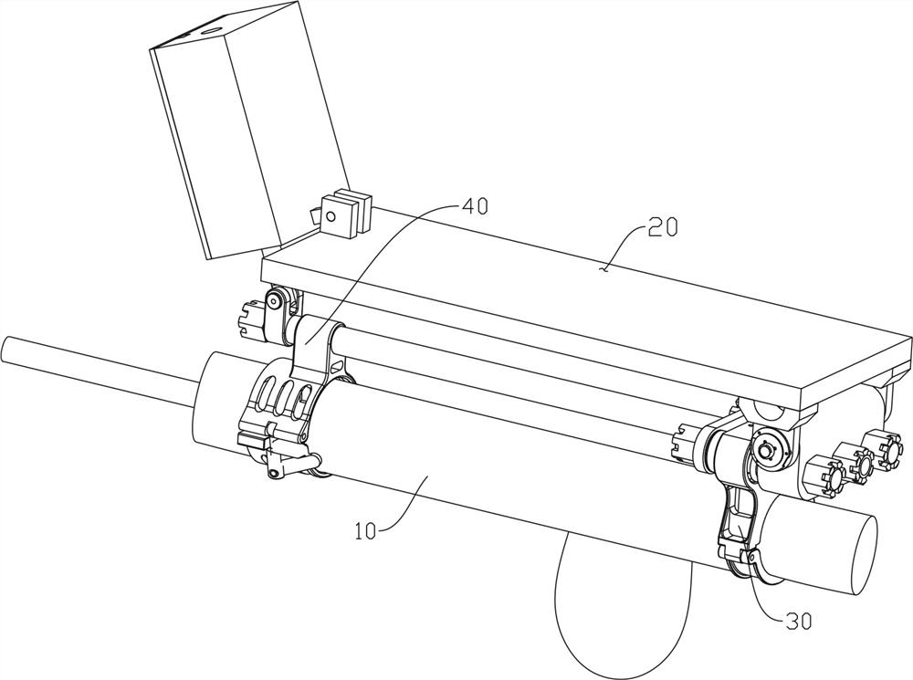
[0037] Such as figure 1 As shown, the present invention provides a kind of unmanned aerial vehicle gun mounting structure through improving here, comprises

[0038] The pitching mechanism 20 is connected with the external required equipment (unmanned aerial vehicle);

[0039] The front sliding sleeve 40 is connected to the lower front part of the pitch mechanism 200; and

[0040] The rear sliding sleeve 30 is connected to the rear part of ...


PUM


Abstract

The invention discloses a firearm mounting structure of an unmanned aerial vehicle, which comprises a pitching mechanism connected with external required equipment; a front sliding sleeve which is connected to the front part of the lower end of the pitching mechanism; and a rear sliding sleeve which is connected to the rear portion of the lower end of the pitching mechanism and used in cooperation with the front sliding sleeve to achieve firearm installation. The front sliding sleeve and the rear sliding sleeve are connected with the firearm in a buckling mode. The firearm mounting structure is reasonable in design and ingenious in structure, the pitch angle of the firearm is adjusted through the ball screw mechanism, the firearm mounting structure is simplified, the weight is reduced, and the cost is saved.

Description

technical field [0001] The invention relates to the field of flight equipment mounting, in particular to an unmanned aerial vehicle gun mounting structure. Background technique [0002] UAVs are more and more widely used in military and civilian fields. Light weapons such as machine guns and howitzers mounted on UAVs can be used to combat small groups of terrorists and illegal armed personnel. Mounted flamethrowers can be used for high-voltage wires disabling. [0003] The UAV-mounted gun rack needs to adjust its posture when aiming and launching. After searching, it is found that the invention patent with the publication number CN206954525U discloses a UAV airborne tower, which can adjust the course of the UAV-mounted gun rack without changing the attitude of the aircraft. Angle and pitch angle, but its structure is relatively complex and there is no buffer device, the recoil force when the firearm is fired will definitely affect the attitude of the aircraft, and there is ...

Claims


Application Information

Patent Timeline
Patent Type & Authority Applications(China)
IPC IPC(8): B64D7/00B64D7/06B64C39/02
CPCB64D7/00B64D7/06B64C39/02B64U2101/00Y02T50/40
Inventor 覃荣峰曾钦勇尹小杰吴晋安段葳杨斌
Owner 成都浩孚科技有限公司
Why Eureka
Try Eureka